Facebook
 Google
 GitHub
 Linkedin
Digital to Analog Conversion
Video Lectures created by Tim Feiegenbaum at North Seattle Community College.
Interfacing Digital and Analog Systems. We're in section 15-4.
Computers are used in nearly every aspect of our daily lives including business, industrial, recreational and personal applications. In many industrial applications, the devices being controlled or monitored are analog. It is important to understand the operation of analog to digital and digital to analog conversion processes. What we're going to do, we're going to look at digital to analog, we're going to also look at analog to digital. We're going to look at it at a very basic level. The devices that are typically used in computers are going to be much more complex than these, but the devices we'll look at, we'll give you an idea of how these actually work.
Digital to Analog Conversion
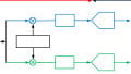
One type of digital to analog converter is shown below. Here we have ... this is a digital to analog converter and notice we have the inputs: A, B, C. Now, this would be digital. Now we would have for example ... it would be one, zero, one, one, possibly a digital value. In the final output we're wanting to have this represent .. be represented in analog type format.
Note that the least significant bit has the highest value input resistor, and so if we were to stretch this out ... if we would maybe have one, one, zero, one like so, that this first bit would be ... this would be the least significant bit and then D here would be the most significant bit. We're going to look at this in a schematic on the next screen. For the moment here we have our inputs and they call these weighted inputs because these are going ... the resistors here are weighted in proportion to the input value. What we're doing is we're going to feed these inputs into this op-amp right here and this is in the inverting amplifier configuration, and the gain of this would be ... remember here we have the feedback resistor. We have R, F over whatever the value of R one, two, three or four R, is going to be set in and we will get a voltage proportional to that value.
Let's just take a quick look at these. If we had the R1, the RF value here is 16k; notice the value of R1 is also 16, so here we'd have a gain of one. The next one would be 16 over eight and then our gain would be two. The next one is 16 over four, our gain would be four. Then the final one is 16 over two and the gain would be eight.
This is our typical binary weighting and when I say that we had one, two, four, eight; one, two, four, and eight, and if we had a binary value, say we had a one, zero, one, zero, we know that the weighting here with this would equate to ten. What we're going to do here is the voltage of the input will cause a current to flow and that current will flow ... remember no current flows into the op-amp. It will flow through this and this will create a voltage proportional to our digital input.
The first one here is going to create this proportional voltage and that is going to be fed into the next op-amp. Now the next op-amp isn't being used to promote gain. The next one is being used more so to ... so that we can precisely set the value of output. You'll notice we have a 10k input resistor here and in the feedback, there is 8.2 and 5k. Now, remember if this was 10k over 10k the game would just be a gain of one. In this case, we have the ability to adjust this and then on the next screen, we'll see where that comes in handy. The second amp is just going to be used for fine tuning actually.
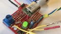
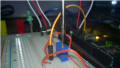
This is the actual circuit as it appears on the workbench and you do have this as one of your schematics. I believe it is circuit 15_36, make that 15_13. I encourage you to go there and look at this. What we'll see here, is here are the input resistors; this is the first amp, this is the second amp and here we have our inputs. As the user, you can go in and you can key in the binary value that you wish and the A, B, C, and D will be the keys that you'll press to set a certain value.
Now, what I have done is I have turned on all of these so this is in binary; this is a one, one, one, one which it equates to 15. Now, what I have also done is that in the output here ... and this is the voltage being measured right here at the output and I went in and measured that, and then I went in and made an adjustment here. I adjusted this such that this was very close to 15 volts. What that equates to is a binary one equates to one volt and a binary two would be two volts and so on and so forth and since this is 15 here, that equates to 15 volts.
This was a very basic digital to analog converter. We come in with a digital value and our output is going to be an analog voltage. Notice that this is only four bits. We have this 15-volt possible output and we have broken that into 15 individual possible outputs. On the next screen here, this would be the sampled output and you'll see. Here we come in and we have one step increments and this would be binary zero, zero, zero, zero and this would be binary one, one, one, one.
Output of DAC
Now, you'll notice that this doesn't look very ... When we think of analog usually we think of continuous chains ... something like this and when we have a digitized output that comes from a ... or an analog better that sources a digital value, it isn't as sign wave solo as we might think. In fact when you do that, if we converted this to analog, if we're doing a sign wave, the sign wave might be up here ... It isn't a perfect sign wave. If you get many bits it gets better but it is never going to be the perfect continuous chains that you see in true analog. This is one of the complaints that audio files will make. They'll say, “Well, digital music will never be as good as analog.” This is the reason why, it's because when you go from digital to analog, as many bits as you add, it is never perfect.
Okay. This is an example of a digital to analog converter. There are many different forms of these and typically this is only a four bit one. In music usually, there is not a record ... at least 24-bit recordings which actually for my ear I can't really tell the difference, but I guess there are those out there that can, but this is digital-analog conversion and there is our simplified circuit and we've introduced this. Next section, we'll go the other way. We'll go analog to digital.
Related Content