Facebook
 Google
 GitHub
 Linkedin
JK Flip-Flop
Video Lectures created by Tim Feiegenbaum at North Seattle Community College.
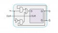
Continuing in 15-3 and we are introducing the JK Flip Flop. Here I have a little schematic symbol here and this schematic symbol probably isn't the best schematic symbol, but it does have all of the inputs and outputs that you would see on a JK Flip Flop. Now what you might note is some things are similar to what we looked at in the D-Type Flip Flop. First of all, we have the set and the reset and we still have the Q and the ? and we still have the clock input. These are all things that you saw on the D-Type.
However, with the JK we have two inputs and these are going to be synchronous inputs and we will have a J and a K. What are we going to say? J and K are synchronous inputs that determine the Flip Flops behavior when a clock transition arrives on the clock input, so again we're going to have a clock coming in and since we have these zero here, that's telling us this one is actually going to clock when the signal goes on the negative edges.
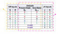
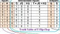
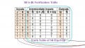
Now here we have the truth table for this device. so with J and K, since there are two possible inputs here, we are going to have four possible states: 0, 1, 2 and 3. Now the first one ... if we had a zero and a zero, now you will notice our outputs again, we have the Qn+1 which we talked about earlier which indicates the state after one clock pulses. Here on this state of zero and zero, we had this Qn and there is no clock pulses present.
What these means is that it indicates the current state. If I have a zero and a zero here, and let's pretend that this was one and a zero, the output is not going to change. In effect when you have zero and zero, the JK Flip Flop isn't going to change states, not disabled if you will, but it is not changing states. It's going to stay in the state that it is in.
Now if we have a zero and a one, let's just put a zero and a one here and we have a clock pulse, then the zero and the one is going to pass straight through to the outputs. Q would become zero and ? would become one and vice versa if we had a one and a zero here on a clock pulse, it would just pass straight through and we would have the same thing - the Qn+1, it would pass straight through. If we had this state, if we had a one and a zero here and we had multiple clock pulses, then this would just stay in the state indefinitely until the J and the K inputs change.
Now if we had a one and a one - now this is a unique part of a JK Flip-Flop. If you have a one and a one here, what the output is going to do is going to toggle, meaning that it's going to change states on every single clock pulse. On this negative going edge, if this is the one and the zero, on the next edge, it's going to be zero one one and then one and zero one and zero zero one one and zero and on and on, so it's going to change states every time that there is a valid edge to clock it. This dictates the truth table for synchronous operation for a JK Flip Flop and as in the data type or the D-Type, if you have a value coming in on either the R or the D, it will override whatever the JK is doing.
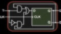
This is an example from your textbook. This is actually figure 1525 in your text book and this is in your multi sim packages 15_25 MSM. I encourage you to go in and run this simulation. This will give you a better understanding of a JK Flip-Flop. This is a very basic configuration; we have the JK set up. Let's look; we have a ground at the bottom of the page. We have the VCC5 or logic in the circuit and we have a switch and you can go in and press the letter D or the space bar and you can activate or deactivate these switches.
Let's look at the current state of the switches and evaluate what we have here. Currently, we have the Ds which is going to ground, so that will put a zero here. It goes through an inverter, so that will put a one on J and that zero goes down here and it puts a zero on K, so we have a 1 0 as an input and then as the clock ... Let's see, this feeding into our clock and this is going to be clocking on a positive edge, so this is going to ground so that will put a low here, is going through the inverter and that will put a high. We have a transition from zero to one when we place that switch in place. When that occurs, what should happen is that one should be passed through to Q and zero should be passed through to zero.
Now, in this case, the high is going to provide us a voltage and just note the lamp here is illuminated. If you go in and do the assimilation and you set this to five volts, you will put a low here and then if you supply a clock and go to five volts and then back up to ground, you should change the state of your light bulb here. I encourage you to go in and do that with the JK Flip Flop. We are going to be doing more JKs that are much more involved in this one and it's crucial for you to get a basic understanding of how this works. If you can go in and do these inputs, you'll get a good feel for how this works.
Okay, so this has introduced the JK Flip Flops and we will be doing a lot more with this in future lessons.