Facebook
 Google
 GitHub
 Linkedin
Sequential Logic
Video Lectures created by Tim Feiegenbaum at North Seattle Community College.
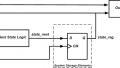
Hey, we are in 15-3 and in this section, we are going to be looking at sequential logic. This section will actually be broken into multiple sections. A sequential logic circuit can have any number of inputs and any number of outputs. Now, this is much like what we discussed in combinational logic. A sequential logic circuit typically has some type of memory element to hold the state of the circuit. Here is a sequential logic circuit and this is just an example.
Notice that we have some combinational logic circuitry on both ends, but in between, we have this memory element. Remember this is what differentiates the sequential logic circuit from a combinational one. It's the presence of memory that can cause the inputs and outputs to ... well in the case of combinational, as soon as you made an input, it immediately impacted the output., but with sequential circuits, you can change the inputs and they don't necessarily immediately change the outputs because there might be something going on in memory.
Now in memory, the whole idea of memory is that you are going to be retaining certain states. Note here if you had one bit of memory, this will equate to two states, one high and one low. That wouldn't be very much memory but it's just for the sake of explanation that would be the case. If you had four bits of memory, then there would be 16 possibles states. If there was eight, it would be 256 16 bits, 65K and 32 there would be four gigs.
Now the memory element also has a clock input which provides timing for changing states.
Flip Flops
Now Flip Flops can be used as memory elements and they are important devices used in many digital applications and they serve as building blocks for more complex integrated circuits. Two of the most common types of Flip Flops are the D-Type and the JK. Flip Flops can operate in two different modes, they can be used asynchronously and they can be used synchronously.
D Type Flip Flop
Okay, first Flip Flop we are going to look at is the D-Type. We have a schematic symbol down here in the right-hand corner. Let's look at the inputs. First, we have the D that's going to be for data, then we have a clock input and then we have the set input and the reset input. Often this is indicated by SD and RD. Then we have two outputs Q and ? and this going to be my indicator here to make it a Not symbol. The Q and ?, if Q is one, then ? would be zero and if Q is zero, then ? would be one, so this will always be opposite each other.
These can be used in asynchronous operation; they can also be used in synchronous operation. First of all, we are going to look at this device used asynchronously. So SD and RD are the asynchronous input. Here we go. Here we have the set and reset. They can override the timing of the clock. When we get into synchronous, we'll find that we have a clock input and it would be moving data through this device. What the set and reset can do, it can override whatever is going on with the clock.
The bubbles on the diagram indicate a low is required to activate the input, so you notice the bubble on the set and the bubble on the reset. What this means is that in order for this to do something with this, so perform the set or the reset function, it's going to be a low that's going to cause that to happen. It won't be high. For example, if we had a high here and a high here, then the set and reset function would be disabled. They are going to be able to do something on a low.
Let's look at the truth table for this device. Here we have inputs and here we have the outputs. Now here we have ... this is the set and this is the reset. Now you will notice zero and zero. This is disallowed because what this will do, this would be saying I want o reset this and I want to reset this. This would be attempting to say we are going to have a high here and a high here. This simply is not allowed. The other three possible inputs that are allowed ... notice here, if we had a zero on set and a one on reset, remember that the zero is going to cause it to activate. The zero here is going to cause to Q to be high and it will cause ? to be low.
Likewise, if we reverse that and have a one here and a zero on reset, it will do just the opposite. It will cause ? to be high and Q to be low. If we had one and one, that would indicate that there is no change and that effectively is disabling the set and reset and when you run this in synchronous operation, this would be the settings that you would have on this two inputs.
Synchronous Operation
That brings us to synchronous operation. When set and reset are disabled, the state of the Flip Flop is controlled by D and the clock. Let's put a high here and a high here and that would disable those. The greater than symbol indicates a signal must have a zero to one transition if a bubble one to zero. We have this symbol right here, this little greater than symbol and what that means is that ... notice it must have a zero to one transition. What that means is we are going to have a clock pulse coming into this device.
What that means is on the positive edge, and that would be as the signal is going positive, that means that would dictate when the transition points occur. If we were to have a little zero here, that would mean that the transition would be on the low. Again if we had the same signal coming in, that would mean it would trigger as the signal goes low. This is often referred to as the edge because the timing is rather precise. The timing would either be on the positive edge or the negative edge and this one without this one would set up for the positive edge.
Now we also have on our truth table here ... we're showing what would we get if we had outputs. Notice, n+1 indicates the next state after the clock pulses. Here we have data coming in and let's pretend that this has been reset and if it's reset, we would have a one here and we would have a zero here. Let's pretend that we have a data element of a high right here. Now notice that the data element is a one but the Q is a zero because this is our input and this was our output, but the output has not changed states because there has not been a valid clock yet.
When we have this positive edge come in, then it would pass this data element to the output and then this would become a one. What this is indicating is if we had a data element, if this had been a zero and then we've got a valid clock, the output would change to zero, but only after the clock pulses. You will notice that the ? is going to begin whatever it is that ? would be Not. Then this one is the one that we just looked at. If it was high, then it would provide the high to the output. That is a quick look at synchronous operation.
Now here we have a question. This question revolves around synchronous operation and this comes from an example in your textbook. Here we have our little schematic of our D-Type Flip Flop. Let's draw a connection between? and D. We are going to make a connection between here and D and supply three clock pulses, okay. Let's draw in three. We are going to have three clock pulses, 1, 2, 3, okay. Initially is that Q equals zero. Our Q is going to be equal to zero, then? must equal one. Then the question is what is the state of the Flip Flop after three pulses, after three pulses?
Let's look at the state of the Flip Flop as we start. Now it has been reset, so Q equals zero and this is going to be our clock right here. I'm going to put another ... this is going to be Q's output. Initially, we have an output Q is zero. This is our starting point right here. Then we are going to supply three clock pulses and then we are going to evaluate where is this at after three clock pulses. We come in; here we have a positive edge. Now note that this is zero but ? is one and ? is up here, so actually, we have a one at this point. At the clock, the data that's on D will be passed to Q so that will make that go high and it will make this go low. Our output from Q at this point goes high and is going to stay high.
Now it's going to stay high until there is another clock. Now depending on what is in D, will determine where that output of Q goes when the clock occurs. Notice at this point ?, we have a high on Q but ? is low ... so the low, now instead of having a one here, now we have a low. Now the clock pulse comes in and now the zero is passed to the output, so now we have a zero here and a one here. At this point, we go low and it will stay low until we get to the next clock pulse.
Next clock pulse, ? is supplying a one here, so now we have the incoming clock and it moves the one to the output and so it goes high and that is the end of our problem because our question was what is the state of the Flip Flop after three pulses. Here we had 1, 2, 3 and the state of our Flip Flop is that it is high after three pulses. This is one use of a D-Type Flip Flop. This is not the only use and we wire this so that? went over to D and like I said, I've not always done that but this is one example just to show you how this work in synchronous operation.
In this section, we looked at synchronous operation; we looked at the inputs and outputs that we would have. We also looked at the asynchronous operation and this is where we would use the set and the reset and remember that those would be lows. Remember that these bubbles would indicate that a low is what would activate the condition. We briefly introduced Flip Flops and we briefly introduced the subject of sequential logic.