 Facebook
 Google
 GitHub
 Linkedin
Introduction to Sequential VHDL Statements
This article will try to develop a better understanding of the sequential statement’s importance in VHDL.
This article will try to develop a better understanding of the sequential statement’s importance in VHDL.
In a previous article, we looked at some concurrent VHDL statements. This article will try to develop a better understanding of the sequential statement’s importance.
Please check out my article on getting started with VHDL for more introductory information.
Why Do We Need Sequential Statements?
VHDL is a hardware description language which can be used to tell the synthesis software what physical components need to be added to the design and how these components are connected to each other. For example, we can use VHDL to describe the circuit in Figure 1.
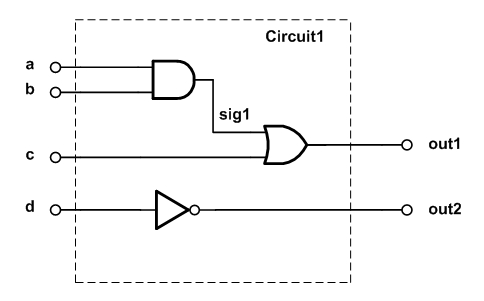
Figure 1
The architecture of the VHDL code for this circuit is shown below.
1	architecture Behavioral of comb1 is
2		signal sig1: std_logic;
3	begin
4		sig1 <= ( a and b );
5		out1 <= ( sig1 or c );
6		out2 <= (not d);
7	end Behavioral;
Consider lines 2, 4, 5, and 6 of this code. Each of these lines has a clear mapping into the hardware schematic shown in Figure 1. For example, line 2 becomes a wire in the final design which is labeled sig1 in the figure. Line 5 specifies an OR gate with the output out1 and the inputs sig1 and c.
As discussed in a previous article, to correctly describe the physical components of Figure 1, the synthesis software evaluates the lines of this code simultaneously. That’s why we call them concurrent statements. So concurrent statements are evaluated simultaneously and have a clear mapping into the hardware components.
With these concurrent statements, we can implement different logic gates. Hence, theoretically, the concurrent statements are sufficient to describe an arbitrary digital circuit.
However, for a number of reasons, VHDL provides us with several sequential statements where the order of statements is important:
Sequential Statements Facilitate Abstract Circuit Description
Sequential statements allow us to describe the abstract behavior of a circuit rather than use low-level components, such as different logic gates, to build the circuit. This abstract behavior description can sometimes make the circuit design simpler. This is due to the fact that human reasoning and algorithms resemble a sequential process.
An example can further clarify this. Assume that we need to design a circuit which receives a four-bit vector, in1, as the input and calculates the number of leading zeros in this vector. How can we design such a circuit using digital gates?
Well, we can find the truth table of the output, simplify it, and then use the logic gates to implement the required equations; however, this seems fairly time-consuming.
What about using some common digital building blocks such as adders and multiplexers to design the circuit? One possible block diagram is shown in Figure 2.

Figure 2
The first element of the input vector, in1(0), is used as the select input of the multiplexer mux0. If this element is zero, the output of mux0, m0, will be one otherwise it will be zero.
For the second multiplexer, we need to check the second element of the input vector as well as the first one. This can be done by using an OR gate. When both of in1(0) and in1(1) are zero, mux1 will output m0 + 1; otherwise, it will pass m0 itself. In this way, we can count the number of leading zeros.
In other words, as long as we have not reached a one, we choose the path coming from the incrementer. After that, however, we simply pass the result of the previous stage unaltered. For example, for the input vector in1=”0011”, we obtain the green path in Figure 3 which gives out1=2.
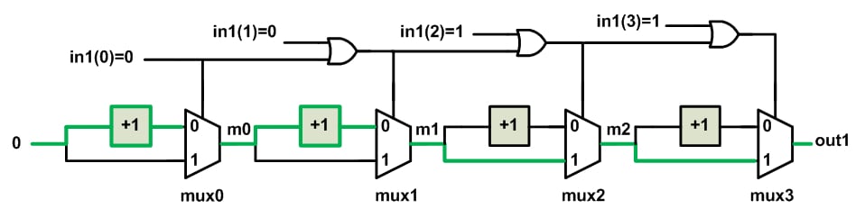
Figure 3
The circuit in Figure 2 is much more intuitive than finding a truth table and, then, using the basic logic gates to implement it. Let’s compare it with the algorithm shown in Figure 4.
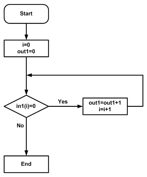
Figure 4
In this case, each bit is examined. If it is zero, count increases by one. If not, we end the process.
This algorithm is essentially based on the human reasoning for counting the number of leading zeros in a sequence of bits. That’s why the method of Figure 4 seems to be easier to understand compared to Figure 2. As this example suggests, our reasoning has generally a sequential nature, i.e., we examine the elements of the input vector one by one and make the appropriate decision.
Moreover, we have abstract descriptions for some operations. For example, when we reach a one in Figure 4, we end the process; however, there is no such operation as “end the process” in the circuit of Figure 2.
To summarize, the algorithm of Figure 4 is sequential and uses abstract descriptions. Since it resembles human reasoning, it’s easier to understand. However, unlike the block diagram of Figure 2, the algorithm of Figure 4 gives us no clues about the underlying hardware structure. Since each of these two methods has their pros and cons, VHDL provides us with the tools to use both of these two techniques.
The concurrent VHDL statements can be used to have a circuit description which is very close to the final hardware, whereas the sequential statements allow us to have a more abstract description of a circuit.
Some Sequential Statements Use Optimized Structures
Sometimes, the use of sequential statements is not only simpler but also safer and more efficient. For example, when using sequential statements to describe particular circuits, such as flip-flops, the synthesis software recognizes the intended circuit and uses some optimized structures to implement it. However, these optimized circuits are not utilized when we describe a flip-flop with logic gates. To read about the danger of deriving a memory element from primitive gates, see section 8.3 of this book. The VHDL description of a D-type flip-flop will be discussed later in this article.
Why Do We Need Processes?
Unlike the concurrent statements, the sequential statements are executed line by line. Hence, we need to separate these two types of code from each other. This is done by enclosing the sequential statements inside a VHDL construct known as a “process”. A “process” can appear anywhere after the “begin” statement of the “architecture”.
The basic structure of a “process” is as follows:
1	process(sensitivity_list)
2	declarations;
3	begin
4	sequential_statements;
5	end process;
As the above structure suggests, the sequential statements are placed between the keywords “begin” and “end”. In this part of the code, the order of the statements is important just like the code in a traditional computer programming.
The declarations part includes any objects that need to be declared and used inside the process. These objects will be local to the process.
The sensitivity_list is the list of the signals which are continuously monitored by the “process” construct. Whenever a signal from the sensitivity_list changes, the “process” will be activated and the sequential statements of the “process” will be executed line by line. Then, the “process” will wait for another change in the sensitivity_list. In this case, it is said that the “process” is suspended. Hence, a “process” has two states: it is either activated due to a change in the sensitivity_list or suspended waiting for a change in the signals of the sensitivity_list.
In future articles, we will discuss the examples of sequential VHDL statements in more detail. However, to get more familiar with the concepts discussed in this article, let’s have a brief look at the VHDL description of a D-type flip-flop (DFF):
The VHDL Code for a Positive-Edge DFF
Figure 5 shows the symbols of a positive-edge DFF (Figure 5(a)) and a negative-edge DFF (Figure 5(b)). These DFFs have three inputs: the data input, the clock input and a reset which are, respectively, shown by D, clk and rst in the figure. The output is denoted by Q.
A flip-flop is an edge-sensitive memory element. This means that the state of the output doesn’t change unless at either the rising edge or the falling edge of the clock. For example, a positive-edge DFF is sensitive to the rising edge of the clock, hence, at the rising edge of the clock, the flip-flop becomes transparent and passes the input D to the output Q. The output will retain its value until the next rising edge of the clock.
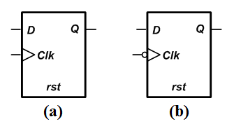
Figure 5(a) a positive-edge DFF and (b) a negative-edge DFF
Now, let’s have a look at the VHDL description of a positive-edge DFF. Please note that the future articles will discuss the sequential statements in detail and the goal of this example is to get familiar with some of the concepts discussed above.
Since the recommended description of a DFF uses a behavioral description, it is rather easy to understand most of the following code even without prior exposure to the topic.
1	library IEEE;
2	use IEEE.STD_LOGIC_1164.ALL;

3	entity DFF is
4	port( d, rst, clk : in std_logic;
5	      q : out std_logic);
6	end DFF;

7	architecture Behavioral of DFF is

8	begin

9		process(clk)
10		begin
11		if (clk'event and clk='1') then
12			if rst='1' then
13				q <= '0';
14			else
15				q <= d;
16			end if;
17		end if;
18	end process;

19	end Behavioral;
This code uses a “process” to describe a DFF.
Line 9 of the code specifies the beginning of the “process”. The clock signal, clk, is specified in the sensitivity list of this “process”. This means that whenever clk changes, either from low to high or vice versa, the sequential statements of the “process” will be executed.
Inside the “process”, there are two “if” statements. The “if” statements of VHDL are similar to the conditional structures utilized in computer programming languages. When the condition after the “if” keyword is true, the statements after the “then” keyword will be executed. Otherwise, the statements after the “else” keyword will be run. However, the “else” branch is optional. For example, in the above code, the outer “if” statement doesn’t have an “else” branch, whereas the inner “if” statement does.
The condition for the first “if” statement is clk’event and clk=’1’. This statement is the key expression to infer a flip-flop. The clk’event returns true when there is a change in the value of the signal clk. ANDing this expression with clk=’1’ means that the value of clk has changed and its current value is ‘1’. This boolean expression will be true at the rising edge of the clock. So the “if” statement of line 11 checks whether the rising edge of the clock has occurred or not. At the rising edge, the statement after the keyword “then”, which is another “if” statement, will be executed.
This second “if” statement checks the reset input rst. If rst is high, the output goes to low; otherwise, it takes the value of the data input D. This is actually the behavioral description of a positive-edge DFF.
After executing the statements inside the “process” body, the “process” becomes suspended which means that it will wait for the next clk edge.
To verify the operation of the above code, examine the ISE simulation of the code given below.
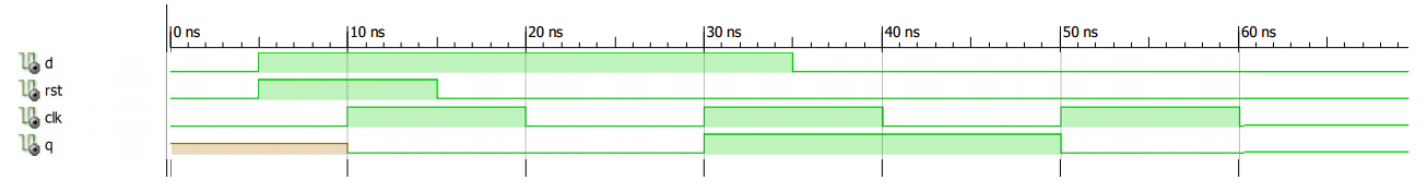
Figure 6
Summary
- Concurrent statements are evaluated simultaneously and have a clear mapping into the hardware components.
- Sequential statements allow us to describe the abstract behavior of a circuit rather than use low-level components, such as different logic gates, to build the circuit. This abstract behavior description can sometimes make the circuit design simpler.
- Sometimes, the use of sequential statements is not only simpler but also safer and more efficient.
- VHDL uses a construct known as a “process” to separate sequential statements from concurrent ones.
To see a complete list of my articles, please visit this page.
Related Content


If process(clk) reacts on clk change, is it necessary to have clk’event in the if statement?