 Facebook
 Google
 GitHub
 Linkedin
What Is VHDL? Getting Started with Hardware Description Language for Digital Circuit Design
This article gives some introductory examples for VHDL coding, a hardware description language used in digital circuit design.
This article goes over VHDL, a hardware description language, and how it's structured when describing digital circuits. We'll also go over some introductory example circuit descriptions and touch on the difference between the "std_logic" and "bit" data types.
VHDL is one of the commonly used Hardware Description Languages (HDL) in digital circuit design. VHDL stands for VHSIC Hardware Description Language. In turn, VHSIC stands for Very-High-Speed Integrated Circuit.
VHDL was initiated by the US Department of Defense around 1981. The cooperation of companies such as IBM and Texas Instruments led to the release of VHDL’s first version in 1985. Xilinx, which invented the first FPGA in 1984, soon supported VHDL in its products. Since then, VHDL has evolved into a mature language in digital circuit design, simulation, and synthesis.
In this article, we will briefly discuss the general structure of the VHDL code in describing a given circuit. We will also become familiar with some commonly used data types, operators, etc. through some introductory examples.
The General Structure of VHDL
Let’s consider a simple digital circuit as shown in Figure 1.
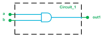
Figure 1. A simple digital circuit.
This figure shows that there are two input ports, a and b, and one output port, out1. The figure suggests that the input and output ports are one bit wide. The functionality of the circuit is to AND the two inputs and put the result on the output port.
VHDL uses a similar description; however, it has its own syntax. For example, it uses the following lines of code to describe the input and output ports of this circuit:
1	entity circuit_1 is
2	    Port ( a : in  STD_LOGIC;
3	           b : in  STD_LOGIC;
4	           out1 : out  STD_LOGIC);
5	end circuit_1;
Let's pull apart what this means, line by line.
Line 1: The first line of the code specifies an arbitrary name for the circuit to be described. The word “circuit_1”, which comes between the keywords “entity” and “is”, determines the name of this module.
Lines 2 to 4: These lines specify the input and output ports of the circuit. Comparing these lines to the circuit of Figure 1, we see that the ports of the circuit along with their features are listed after the keyword “port”. For example, line 3 says that we have a port called “b”. This port is an input, as indicated by the keyword “in” after the colon.
What does the keyword “std_logic” specify? As we will discuss later in this article, std_logic is a commonly used data type in VHDL. It can be used to describe a one-bit digital signal. Since all of the input/output ports in Figure 1 will transfer a one or a zero, we can use the std_logic data type for these ports.
Line 5: This line determines the end of the “entity” statement.
Hence, the entity part of the code specifies 1) the name of the circuit to be described and 2) the ports of the circuit along with their characteristics, namely, input/output and the data type to be transferred by these ports. The entity part of the code actually describes the interface of a module with its surrounding environment. The features of the above circuit which are specified by the discussed “entity” statement are shown in green in Figure 1.
In addition to the interface of a circuit with its environment, we need to describe the functionality of the circuit. In Figure 1, the functionality of the circuit is to AND the two inputs and put the result on the output port. To describe the operation of the circuit, VHDL adds an “architecture” section and relates it to circuit_1 defined by the entity statement. The VHDL code describing the architecture of this circuit will be
6	architecture Behavioral of circuit_1 is

8	begin
9		out1 <= ( a and b );
10	end Behavioral;
Line 6: This line gives a name, “Behavioral”, for the architecture that will be described in the next lines. This name comes between the keywords “architecture” and “of”. It also relates this architecture to "circuit_1". In other words, this architecture will describe the operation of “circuit_1”.
Line 8: This specifies the beginning of the architecture description.
Line 9 Line 9 uses the syntax of VHDL to describe the circuit’s operation. The AND of the two inputs a and b is found within the parentheses, and the result is assigned to the output port using the assignment operator “<=”.
Line 10 This specifies the end of the architecture description. As mentioned above, these lines of code describe the circuit’s internal operation which, here, is a simple AND gate (shown in blue in Figure 1).
Putting together what we have discussed so far, we are almost done with describing “Circuit_1” in VHDL. We obtain the following code:
1	entity circuit_1 is
2	    Port ( a : in  STD_LOGIC;
3	           b : in  STD_LOGIC;
4	           out1 : out  STD_LOGIC);
5	end circuit_1;
-----------------------------------------------------
6	architecture Behavioral of circuit_1 is
8	begin
9		out1 <= ( a and b );
10	end Behavioral;
However, we still need to add a few more lines of code. These lines will add a library that contains some important definitions, including the definition of data types and operators. A library may consist of several packages (see Figure 2 below). We will have to make the required package(s) of a given library visible to the design.
Since the above example uses the data type “std_logic”, we need to add the package “std_logic_1164” from “ieee” library to the code. Note that the logical operators for the std_logic data type are also defined in the “std_logic_1164” package—otherwise we would have to make the corresponding package visible to the code. The final code will be
1	library ieee;
2	use ieee.std_logic_1164.all
3	entity circuit_1 is
4	    Port ( a : in  STD_LOGIC;
5	           b : in  STD_LOGIC;
6	           out1 : out  STD_LOGIC);
7	end circuit_1;
-----------------------------------------------------
8	architecture Behavioral of circuit_1 is
9	begin
10		out1 <= ( a and b );
11	end Behavioral;
Here, we create two new lines to go above what we've alreeady created. The first line adds the library “ieee” and the second line specifies that the package “std_logic_1164” from this library is required. Since “std_logic” is a commonly used data type, we almost always need to add the “ieee” library and the “std_logic_1164” package to the VHDL code.
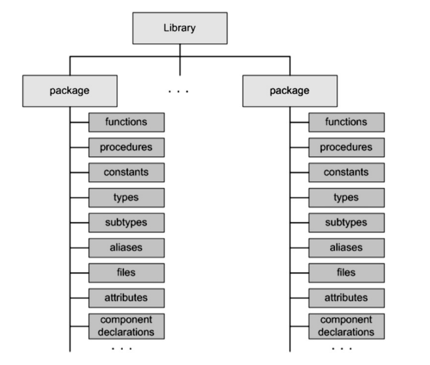
Figure 2. A library may consist of several packages. Image courtesy of VHDL 101.
We can use the Xilinx ISE simulator to verify the operation of the above VHDL code. (For introductory information on ISE, see this tutorial.)
Now that we are familiar with the fundamental units in VHDL code, let’s review one of the most important VHDL data types, i.e., the “std_logic” data type.
The "std_logic" Data Type (vs. "bit")
As mentioned above, the “std_logic” data type can be used to represent a one-bit signal. Interestingly, there is another VHDL data type, “bit”, which can take on a logic one or a logic zero.
So why do we need the std_logic data type if the “bit” data type already covers the high and low states of a digital signal? Well, a digital signal is actually not limited to logic high and logic low. Consider a tri-state inverter, as shown in Figure 3.
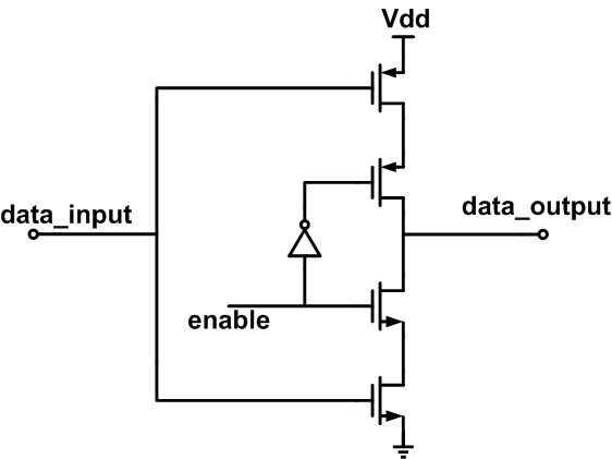
Figure 3. The transistor-level schematic of a tri-state inverter.
When “enable” is high, “data_output” is connected to either Vdd or ground; however, when “enable” is low, “data_output” is floating, i.e., it does not have a low-impedance connection to Vdd or ground but instead presents a “high impedance” to the external circuitry. The “std_logic” data type allows us to describe a digital signal in high-impedance mode by assigning the value ‘Z’.
There is another state—i.e., in addition to logic high, logic low, and high impedance—that can be used in the design of digital circuits. Sometimes we don’t care about the value of a particular input. In this case, representing the value of the signal with a “don’t care” can lead to a more efficient design. The “std_logic” data type supports the “don’t care” state. This enables better hardware optimization for look-up tables.
The “std_logic” data type also allows us to represent an uninitialized signal by assigning the value ‘U’. This can be helpful when simulating a piece of code in VHDL. It turns out that the “std_logic” data type can actually take on nine values:
- ‘U’: Uninitialized
- ‘1’ : The usual indicator for a logic high, also known as ‘Forcing high’
- ‘0’: The usual indicator for a logic low, also known as ‘Forcing low’
- ‘Z’: High impedance
- ‘-’: Don’t care
- ‘W’: Weak unknown
- ‘X’: Forcing unknown
- ‘H’: Weak high
- ‘L’: Weak low
Among these values, we commonly use ‘0’, ‘1’, ‘Z’, and ‘-’.
Let’s look at an example.
Example 1
Write the VHDL code for the circuit in Figure 4.
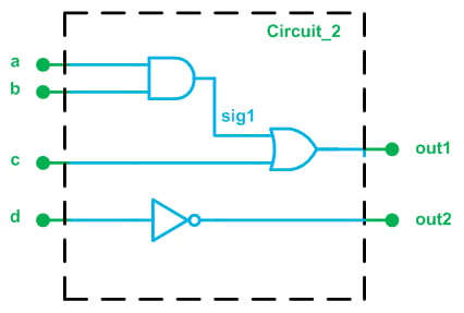
Figure 4.
The general procedure is almost the same as the previous example. The code will be as follows:
1	library IEEE;
2	use IEEE.STD_LOGIC_1164.ALL;
----------------------------------------------------
3	entity circuit_2 is
4	    Port ( a : in  STD_LOGIC;
5	           b : in  STD_LOGIC;
6	           c : in  STD_LOGIC;
7	           d : in  STD_LOGIC;
8	           out1 : out  STD_LOGIC;
9	           out2 : out  STD_LOGIC);
10	end circuit_2;
-----------------------------------------------------
11	architecture Behavioral of circuit_2 is
12		signal sig1: std_logic;
13	begin
14		sig1 <= ( a and b );
15		out1 <= ( sig1 or c );
16		out2 <= (not d);

17	end Behavioral;
Lines 1 and 2: These lines add the required library and package to the code. Since the “std_logic” data type is used, we have to add the “std_logic_1164” package.
Lines 3-10: These lines specify the name of the module along with its input/output ports. This part of the code corresponds to the parts of Figure 4 that are in green.
Lines 11-17: This part of the code describes the operation of the circuit (those parts of Figure 4 that are in blue). As you may have noticed, there is one internal node in Figure 4; it is labeled “sig1”. We use the “port” statement from “entity” to define the input/output ports, but how can we define the internal nodes of a circuit? For this, we use the “signal” keyword.
In line 12 of the above code, the “signal” keyword tells the synthesis software that there is a node in the circuit labeled “sig1”. Similar to the definition of the ports, we use the keyword “std_logic” after the colon to specify the required data type. Now we can assign a value to this node (line 14) or use its value (line 15).
Example 2
Write the VHDL code for the circuit in Figure 5.
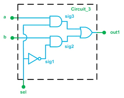
Figure 5.
This circuit is a two-to-one multiplexer. When “sel” is high, the output of the lower AND gate will be low regardless of the value of “b”. We may say that the AND gate prevents “b” from propagating to “sig2”. On the other hand, since “sel” is high, the output of the upper AND gate will follow “a”. Or, equivalently, “a” will reach “sig3”. Since “sig2” is low in this case, the output of the OR gate will be the same as “sig3”. Hence, when “sel” is high, “out1” will be the same as “a”.
A similar discussion will reveal that, when “sel” is low, “out1” will take on the value of “b”. Hence, based on the value of “sel”, we can allow one input or the other one to reach the output. This is called multiplexing and the circuit is called a multiplexer.
We can describe the circuit of Figure 5 using the following code:
1	library IEEE;
2	use IEEE.STD_LOGIC_1164.ALL;
-----------------------------------------------------
3	entity circuit_3 is
4	    Port ( a : in  STD_LOGIC;
5	           b : in  STD_LOGIC;
6	           sel : in  STD_LOGIC;
7	           out1 : out  STD_LOGIC);
8	end circuit_3;
-----------------------------------------------------
9	architecture Behavioral of circuit_3 is
10		signal sig1, sig2, sig3: std_logic;
11	begin
12		sig1 <= ( not sel );
13		sig2 <= ( b and sig1 );
14		sig3 <= ( a and sel );
15		out1 <= ( sig2 or sig3 );

16	end Behavioral;
Summary
In this article, we've discussed what VHDL is, how it's structured, and introduced some examples of how it's used to describe digital circuits. You should now have a better understanding of the following points:
- The “entity” part of the code specifies 1) the name of the circuit to be described and 2) the ports of the circuit; it establishes the interface between a module and its surrounding environment.
- The “architecture” part of the code describes the circuit’s internal operation.
- VHDL libraries contain important definitions, including the definition of data types and operators. A library itself may consist of several packages.
- We almost always need to add the “ieee” library and the “std_logic_1164” package to our VHDL code.
- Among the possible values for the "std_logic" data type, we commonly use ‘0’, ‘1’, ‘Z’, and ‘-’.
To see a complete list of my articles, please visit this page.
Featured image courtesy of HuMANDATA LTD.


Thanks for the write-up! Learned Verilog as an undergrad and never really looked at VHDL.
enjoyed the ‘well thought of’ introduction!