Facebook
 Google
 GitHub
 Linkedin
Sequential VHDL: If and Case Statements
This article will review two important sequential statements in VHDL, namely “if” and “case” statements.
This article will review two important sequential statements, namely “if” and “case” statements.
The previous article on sequential statements in VHDL, this series explained that sequential statements allow us to describe a digital system in a more intuitive way.
This article will review two important sequential statements, namely “if” and “case” statements.
If you'd like to review more basic concepts before continuing, please check out my article on the basics of VHDL.
Sequential Circuits vs Sequential Statements
It’s important to note that sequential VHDL is not necessarily used to describe a sequential circuit. These are two different concepts.
Sequential VHDL is the part of the code that is executed line by line. These statements can be used to describe both sequential circuits and combinational ones.
A sequential circuit is one that uses memory elements, such as registers, to store data as the internal state of the circuit. The output of a sequential circuit depends on both the circuit inputs and its internal states. For example, consider a three-bit counter with a clock input. Assume that with each rising edge of the clock, the output of the counter increases by one. We’ll observe the sequence 000, 001, 010, …, 111 at the counter output. Such a circuit is sequential because its output depends on both the input clock and the current value of the counter.
Sequential VHDL allows us to easily describe both sequential circuits and combinational ones.
“If” Statement
The “if” statements of VHDL are similar to the conditional structures utilized in computer programming languages. Listing 1 below shows a VHDL "if" statement.
Listing 1
1 if Expression_1 then
2 Output_signal <= Value1;
3 elsif Expression_2 then
4 Output_signal <= Value2;
5 elsif Expression_3 then
6 Output_signal <= Value3;
7 else
8 Output_signal <= Value4;
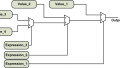
9 end if;There are boolean expressions after the keywords “if” and “elsif”. These boolean expressions are either true or false. The boolean expressions will be evaluated successively until a true expression is found. The assignment corresponding to this true expression will be performed. If none of these expressions are true, the assignment after the “else” keyword will be executed. The conceptual diagram of the above code is shown in Figure 1.
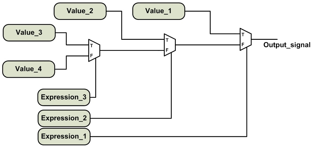
Figure 1. The conceptual implementation of an “if-elsif-else” statement.
If you’ve read the previous articles in the series, you may have recognized that the above diagram is exactly the same as the implementation of a conditional signal assignment or a “when/else” assignment found in Concurrent Conditional and Selected Signal Assignment in VHDL.
Similar to a “when/else” statement, the “if” statement incorporates priority-encoded logic. This means that the expressions of an “if” statement are evaluated successively and that the expressions evaluated first have a higher priority compared to the later ones. The “if” statement can be considered as a sequential equivalent of the “when/else” statement. For example, we can use the following “when/else” statement to implement the conceptual diagram shown in Figure 1.
1	output_signal <= value_1	when	expression_1 else
2			 value_2	when	expression_2 else
3			 value_3	when   expression_3  else
4			 value_4;
However, the “if” statement is more general than a “when/else”, because VHDL allows us to perform multiple assignments in each “then” branch of an “if” statement. The following code illustrates an “if” statement with two assignments in each “then” branch.
Listing 2
1	if Expression_1 then
2		Output_signal_a <= Value_a1;
3		Output_signal_b <= Value_b1;
4	elsif Expression_2 then
5		Output_signal_a <= Value_a2;
6		Output_signal_b <= Value_b2;
7	elsif Expression_3 then
8		Output_signal_a <= Value_a3;
9		Output_signal_b <= Value_b3;
10	else
11		Output_signal_a <= Value_a4;
12		Output_signal_b <= Value_b4;
13	end if;
We can extend the conceptual implementation shown in Figure 1 to arrive at the implementation of the code in Listing 2. In this case, we’ll need to employ two different chains of multiplexers for the two output signals output_signal_a and output_signal_b. The circuits implementing the boolean expressions will be shared between the two chains of multiplexers.
Note that the “elsif” and “else” branches of an “if” statement are optional. Hence, the simplest form of an “if” statement will be
1	if Expression_1 then
2		Output_signal <= Value1;
3	end if;
In such cases, we should be careful to avoid undesired latch inferences. We’ll discuss latch inference in great detail in a future article. Let’s use the “if” statement to describe a one-bit 4-to-1 multiplexer.
Example 1: Use the “if” statement to describe a one-bit 4-to-1 multiplexer. The inputs to be selected are a, b, c, and d. A two-bit signal, sel, is used to choose the desired input and assign it to out1.
The code will be as follows:
1	library IEEE;
2	use IEEE.STD_LOGIC_1164.ALL;

3	entity Mux2 is
4	    Port ( a : in  STD_LOGIC;
5	           b : in  STD_LOGIC;
6	           c : in  STD_LOGIC;
7	           d : in  STD_LOGIC;
8	           sel : in  STD_LOGIC_VECTOR (1 downto 0);
9	           out1 : out  STD_LOGIC);
10	end Mux2;

11	architecture Behavioral of Mux2 is

12	begin

13		process(a, b, c, d, sel)
14		begin
15			if sel="00" then
16				out1 <= a;
17			elsif sel="01" then
18				out1 <= b;
19			elsif sel="10" then
20				out1 <= c;
21			else
22				out1 <= d;
23			end if;
24		end process;

25	end Behavioral;
The above code is an example of using a process, which is based on sequential statements, to describe a combinational circuit. Note that all of the input signals of the multiplexer are present in the process sensitivity list. Hence, whenever any of these signals changes, the process will be executed and, if necessary, the output, out1, will be updated. In general, when using a process to describe a combinational circuit, we need to include all of the inputs in the sensitivity list.
An ISE simulation of the above code is shown in Figure 2. As you can see, from 0 ns to 300 ns, we have sel=“00”, hence, out1 is following the value of a. You can easily verify the operation of the circuit in the rest of the simulation.
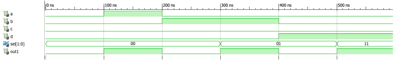
Figure 2
For more examples of using the “if” statement, see the VHDL code for a positive-edge DFF and a counter in previous articles of this series.
The “Case” Statement
In a previous article, we saw that synthesis software maps a “with/select” statement into a multiplexer. The sequential equivalent of the “with/select” statement is the “case” statement (though a “case” statement is more general than a “with/select” statement). The simple form of a “case” statement is as follows:
1 case control_expression is
2 when option_1 =>
3 output_signal <= value_1;
4 when option_2 =>
5 output_signal <= value_2;
...
6 when option_n =>
7 output_signal <= value_n;
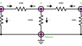
8 end case;The above code will map into an n-to-one multiplexer, as shown in Figure 3. The value of the control_expression, which comes between the keywords “case” and “is”, will be compared with the n possible options, i.e., option_1, option_2, ..., option_n. When a match is found, the assignment corresponding to that particular option will be performed. For example, if control_expression is the same as option_2, then the second “when” branch will assign value_2 to output_signal.
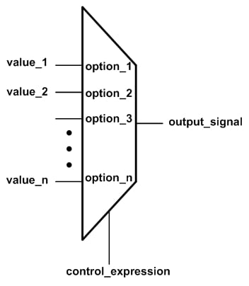
Figure 3. A multiplexer selects one of its n inputs based on the value of control_expression.
Note that the functionality of the multiplexer in Figure 3 could also be implemented using a “with/select” statement instead of a “case” statement:
1	with control_expression select
2		output_signal <= value_1	when	option_1,
3				 value_2	when	option_2,
4				...
5				 value_n	when	option_n;
This is why we can consider the “case” statement to be the sequential equivalent of the “with/select” statement; however, the “case” statement is more general. For example, we can have an “if” statement or multiple signal assignments in each “when” branch of a “case” statement.
Note that, just like the options of a “with/select” statement, the options of a “case” statement must be mutually exclusive, i.e., one option cannot be used more than once. Moreover, all the possible values of the control_expression must be included in the set of the options. We can use the keyword “others” in the final “when” branch of the “case” statement to make sure that all the possible values of the control_expression are covered. The following example clarifies this point.
Example 2: Use the “case” statement to describe a one-bit 4-to-1 multiplexer. The inputs to be selected are a, b, c, and d. A two-bit signal, sel, is used to choose the desired input and assign it to out1.
The code for this multiplexer is given below:
library IEEE;
use IEEE.STD_LOGIC_1164.ALL;

entity Mux2 is
    Port ( a : in  STD_LOGIC;
           b : in  STD_LOGIC;
           c : in  STD_LOGIC;
           d : in  STD_LOGIC;
           sel : in  STD_LOGIC_VECTOR (1 downto 0);
           out1 : out  STD_LOGIC);
end Mux2;

architecture Behavioral of Mux2 is

begin
	process(a, b, c, d, sel)
	begin
	case sel is
		when "00" =>
			out1 <= a;
		when "01" =>
			out1 <= b;
		when "10" =>
			out1 <= c;
		when others =>
			out1 <= d;
	end case;
	end process;

end Behavioral;
Note that since the std_logic data type can take values other than “0” and “1”, the last “when” branch uses the keyword “others” to take all the possible values of sel into account. The following figure shows the simulation of this code using the Xilinx ISE simulator. You can easily verify that the circuit operates as expected.
Figure 4
Summary
- Sequential VHDL code is executed line by line.
- A sequential circuit uses memory elements, such as registers, to store the internal state of the circuit. The output of a sequential circuit depends on both the inputs to the circuit and the circuit’s internal states.
- Similar to a “when/else” statement, the “if” statement incorporates priority-encoded logic. This means that the expressions of an “if” statement are evaluated successively, with higher priority given to the earlier expressions.
- The “if” statement is more general than the “when/else” statement.
- When using a process to describe a combinational circuit, we need to include all of the inputs in the sensitivity list.
- We can think of the “case” statement as the sequential equivalent of the “with/select” statement; however, the “case” statement is more general.
- The options of a “case” statement must be mutually exclusive, and all possible values of the control_expression must be included in the set of options.
To see a complete list of my articles, please visit this page.