Facebook
 Google
 GitHub
 Linkedin
Integer and Its Subtypes in VHDL
This article will discuss the VHDL integer data type.
This article will discuss the VHDL integer data type.
VHDL provides us with several options for the data type of the objects. We’ve already looked at std_logic, std_logic_vector, and enumerated types, and the previous article discussed data type classification based on the package that defines the type. This article will continue the data type discussion, focusing on the integer data type.
Classifying VHDL Data Types
In the previous article, we classified the VHDL data types based on the package that gives the type definition. This is shown in Figure 1.
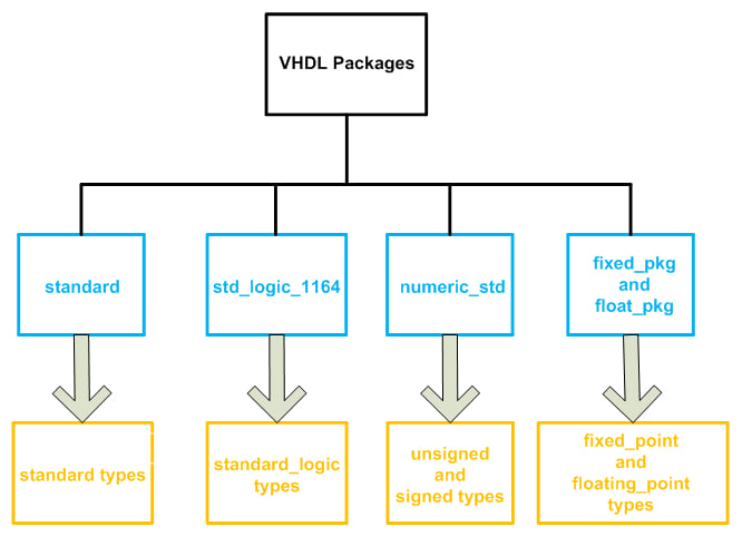
Figure 1. VHDL packages (shown in blue) and the data types defined in each package (shown in orange).
We also gave some details about the “standard types” from the “standard” package. This article will discuss the integer data type and its subtypes.
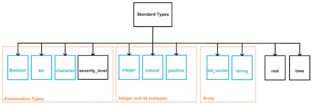
Figure 2. The “integer” data type and its subtypes are defined in the “standard” package.
The Integer Data Type
We can use the integer data type to define objects whose value can be a whole number. For example, the following lines define the signal sig_int of type integer and assign a whole number, 4, to it.
signal sig_int : integer;
sig_int <= 4;
As shown in Figure 2, the integer data type is in the “standard types” category which is defined in the “standard” package from “std” library. As discussed in a previous article, we don’t need to explicitly make the “standard” package and the “std” library visible to the design.
The following code shows a simple example where two inputs of type integer, in1 and in2, are added together and the result is assigned to out1.
1	library IEEE;
2	entity IntegerTest1 is
3		port( in1, in2 : in integer;
4		      out1 : out integer);
5	end IntegerTest1;
6	architecture Behavioral of IntegerTest1 is
7	begin
8		out1 <= in1 +in2;
9	end Behavioral;
Figure 3 shows an ISE simulation of the above code. The decimal equivalent of the input/output values are shown in this figure. For example, from 200 ns to 300 ns, the inputs in1 and in2 are 3 and -1, respectively. So the output, out1, is equal to 3+(-1)=2.
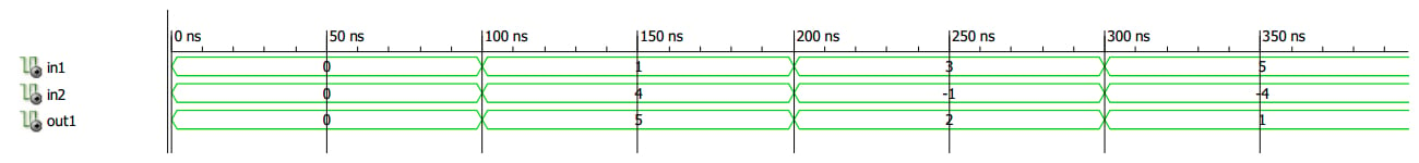
Figure 3.
With the integer data type, we are not directly involved in the bit-level definitions; however, it’s clear that the implementation will use a number of bits to represent the defined signals. How many bits will be used to represent the integer signals in the above code? VHDL doesn’t specify the exact number of bits, but any VHDL implementation should support at least a 32-bit realization for the integer type. According to the standard, this 32-bit realization allows assigning a whole number in the range of $$-(2^{31}-1)$$ to $$+(2^{31}-1)$$ to an object of type integer.
Sometimes we are dealing with limited values, and it’s not efficient to use a 32-bit signal to represent a small value. For example, assume that the input in1 takes on a value between 0 to 45. So, we can use a six-bit signal instead of a 32-bit representation because $$45_{10}=101101_{2}$$. Moreover, assume that the other input, in2, has a value in the range of -45 to 45, so a signed representation must be used. Considering the sign bit, we need only seven bits instead of the default 32 bits because the two’s complement representation of -45 is $$1010011$$. To achieve this significant reduction in the use of FPGA resources, we can simply specify the range of the signals as in the following code:
1	library IEEE;
2	entity IntegerTest1 is
3		port( in1 : in integer range 0 to 45;
		      in2 : in integer range -45 to 45;
4		      out1 : out integer range -45 to 90);
5	end IntegerTest1;
6	architecture Behavioral of IntegerTest1 is
7	begin
8		out1 <= in1 +in2;
9	end Behavioral;
This code assumes that the inputs in1 and in2 are in the ranges 0 to 45 and -45 to 45, respectively. Since out1 is equal to in1+in2, the range of out1 will be from -45 to 90. Limiting the range of the integers reduces the amount of FPGA resources that are required for implementing the design. Moreover, it gives us a means of checking for errors in the early stages of the design. For example, assume that out1 represents an angle and, from system specifications, we know that the value of this angle is restricted to the range -45 to 90.
As given in the above code, we can apply this range to the definition of the object out1. Now, if we make any mistake that forces the value of out1 to be outside the specified range, the simulator software will throw an error and identify the line of code that involves the invalid assignment. For example, if we specify the range of out1 as -45 to 89 and then assign the value 45 to both in1 and in2, the ISIM simulator will stop simulation with the following error (ISim is the name of the simulator that is included in the ISE software):
ERROR: In process IntegerTest1.vhd:17
value 90 is out of valid range -45 to 89
INFO: Simulator is stopped.
(In my simulation code, line 17 has the assignment out1 <= in1 + in2.) Note that the ISIM simulator does not catch these range-related errors by default; you must enable the software’s “value range check” option. If this option is not enabled, the simulation will not stop and any value can be assigned to an integer that is declared to have a limited range.
Note that specifying a smaller range does not always mean that we can represent the signal with a smaller number of bits. For example, consider the following declarations:
1	signal sig_int1 : integer range 0 to 7;
2	signal sig_int2 : integer range 6 to 7;
3	signal sig_int3 : integer range -8 to 7;
4	signal sig_int1 : integer range -8 to 0;
The first two declarations require a three-bit representation even though the second declaration has a smaller range. Similarly, the third and fourth declarations both need four bits.
Intermediate Calculations with Limited Integers
It’s important to note that while the simulator will check for the range of values assigned to an integer, this check occurs only when actually assigning a value, not during the intermediate calculations. To clarify this, consider the following code:
1	library IEEE;
2	entity IntegerTest1 is
3		port( in1 : in integer range 0 to 45;
		      in2 : in integer range -45 to 45;
4		      out1 : out integer range -46 to 89);
5	end IntegerTest1;
6	architecture Behavioral of IntegerTest1 is
7	begin
8		out1 <= (in1 + in2) - 1;
9	end Behavioral;
Let’s assume that in1 and in2 are both equal to 45. In line 8, in1+in2 will be evaluated first. So the expression inside the parentheses will be equal to 90 which is outside the range that out1 can take. However, this is an intermediate calculation and, since no assignment is involved yet, the simulator will not check the range of the result. Then the subtraction will be performed, i.e., 90-1=89. Finally, the value 89, which is now inside the defined range, will be assigned to out1. An ISE simulation for the above code is shown below.
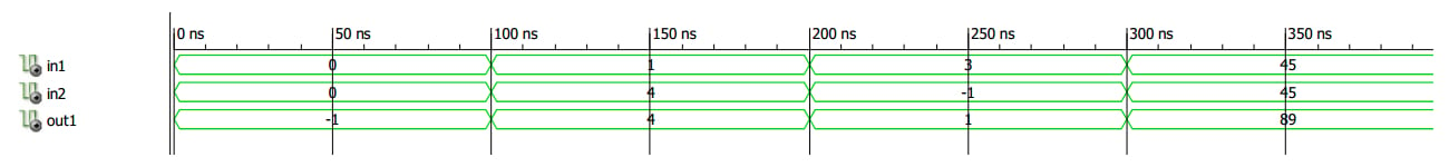
Figure 4.
In principle, the intermediate calculations are performed employing the standard range of the integer type, i.e., 32 bits. However, since this won’t be an optimal implementation, the synthesis software will perform some optimizations according to the nature of the utilized operators. For example, if an intermediate operation is to add two integers with range 0 to 15, the result of this intermediate calculation will have enough bits to represent the largest possible value, which is 30 (for more details see Section 4.6.4 of this book).
The Predefined Subtypes of Integer
A subtype of a given type restricts the type range. As shown in Figure 2, “integer” has two predefined subtypes:
subtype natural is integer range 0 to integer'high;
subtype positive is integer range 1 to integer'high;
The value integer’high represents the highest value of the integer. The “natural” subtype creates a signal that can take all non-negative integers (i.e., 0, 1, 2, 3, …), and the “positive” subtype creates a signal that can take all positive integers (1, 2, 3, …). Though this implementation is consistent in the context of VHDL, keep in mind that the mathematical community does not agree upon whether zero is included in the set of natural numbers.
Summary
- The integer data type and its subtypes are defined in the “standard” package from the “std” library. The integer type is used to define objects whose value is always a whole number.
- VHDL doesn’t specify the exact number of bits for the integer type, but any VHDL implementation should support at least a 32-bit realization.
- We can specify the range of values that an object of type integer is going to have.
- Limiting the range reduces the FPGA resources needed to implement the design. Moreover, it gives us a means of checking for errors in the early stages of the design.
- The ISIM simulator does not catch range-related errors by default; you must enable the “value range check” option.
- This check occurs only when assigning a value, not during intermediate calculations.
To see a complete list of my articles, please visit this page.