Facebook
 Google
 GitHub
 Linkedin
Simplifying VHDL Code: The Std_Logic_Vector Data Type
This article will review the "std_logic_vector" data type which is one of the most common data types in VHDL.
This article will review the "std_logic_vector" data type which is one of the most common data types in VHDL.
In a previous article on the VHDL hardware description language, we discussed the basic structure of VHDL code through several introductory examples. This article will review one of the most common data types in VHDL, i.e., the “std_logic_vector” data type.
We will first discuss the fact that vectors allow us to have a more compact and readable VHDL description, especially when dealing with large circuits. Then, after reviewing some important features of the “std_logic_vector” data type, we will go over some coding styles that can help us avoid mistakes when utilizing vectors.
Why Do We Need Vector Data Types?
Consider the simple circuit in Figure 1, which was discussed in the previous article.
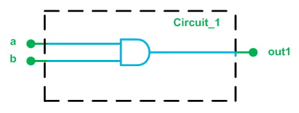
Figure 1. A simple digital circuit.
Here is the VHDL code for this circuit:
1	library ieee;
2	use ieee.std_logic_1164.all;
3	entity circuit_1 is
4	    Port ( a : in  STD_LOGIC;
5	           b : in  STD_LOGIC;
6	           out1 : out  STD_LOGIC);
7	end circuit_1;
-----------------------------------------------------
8	architecture Behavioral of circuit_1 is
9	begin
10		out1 <= ( a and b );
11	end Behavioral;
Now, assume that we need to write the VHDL code for the circuit in Figure 2.
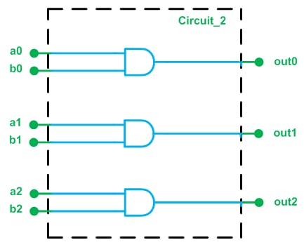
Figure 2.
We can extend the previous code to obtain the VHDL description of Figure 2 as
1	library ieee;
2	use ieee.std_logic_1164.all;
3	entity circuit_2 is
4	    Port ( a0 : in  STD_LOGIC;
5		   a1 : in STD_LOGIC;
6		   a2 : in STD_LOGIC;
7		   b0 : in  STD_LOGIC;
8		   b1 : in STD_LOGIC;
9		   b2 : in STD_LOGIC;
10	           out0 : out  STD_LOGIC;
11	           out1 : out  STD_LOGIC;
12		   out2 : out  STD_LOGIC);
13	end circuit_2;
-----------------------------------------------------
14	architecture Behavioral of circuit_2 is
15	begin
16		out0 <= ( a0 and b0 );
17		out1 <= ( a1 and b1 );
18		out2 <= ( a2 and b2 );
19	end Behavioral;
The above code is correct; however, we will see that it’s possible to have a more compact and readable VHDL description for this circuit. The drawback to the above code is that it presents each of the input/output ports as individual signals and doesn’t establish any relationship between them.
Let’s consider an alternative way of depicting the circuit in Figure 2.
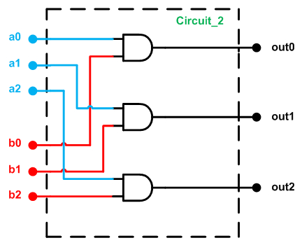
Figure 3.
Figure 3 suggests that we can consider a0, a1, and a2 as a three-bit input port called, for example, a_vec. Similarly, the input ports b0, b1, and b2 can be grouped as another three-bit input port called b_vec. What the circuit does is AND an element of a_vec with a corresponding element of b_vec. This may seem like a simple idea, but we will see in a minute how this way of thinking makes the code more readable.
The “Std_Logic_Vector” Data Type
To represent a group of signals, VHDL uses vector data types. To access an element of a vector, we need to define an index. For example, assume that, as shown in Figure 4, we use a vector of length three, a_vec, to represent three values: val_0, val_1, and val_2. To access the value of an element from this vector, we can use the index numbers. For example, a_vec(2) will give the value of the rightmost element of the vector in Figure 4, which is val_2.
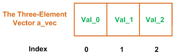
Figure 4. The three-element vector a_vec.
The VHDL keyword “std_logic_vector” defines a vector of elements of type std_logic. For example, std_logic_vector(0 to 2) represents a three-element vector of std_logic data type, with the index range extending from 0 to 2.
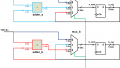
Let’s use the “std_logic_vector” data type to describe the circuit in Figure 3. We will use three vectors a_vec, b_vec, and out_vec to represent the blue, red, and black ports of Figure 3, respectively. With the new naming for the ports, we obtain the following figure.
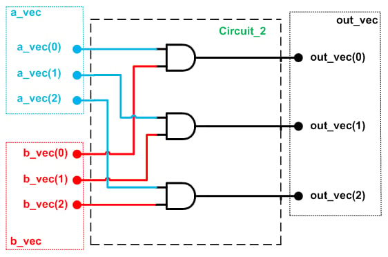
Figure 5.
The VHDL code for Figure 5 is given below.
1	library ieee;
2	use ieee.std_logic_1164.all;
3	entity circuit_2 is
4	    Port ( a_vec : in  STD_LOGIC_VECTOR(0 to 2);
5	           b_vec : in  STD_LOGIC_VECTOR(0 to 2);
6	           out_vec : out  STD_LOGIC_VECTOR(0 to 2));
7	end circuit_2;
-----------------------------------------------------
8	architecture Behavioral of circuit_2 is
9	begin
10		out_vec <= ( a_vec and b_vec );
11	end Behavioral;
Lines 4 to 6 of this code use the “std_logic_vector” data type for the input/output ports of the circuit. Note that the AND operation in line 10 will be applied to the corresponding elements of the two vectors a_vec and b_vec, i.e., a_vec(0) is ANDed with b_vec(0) and the result is assigned to out_vec(0), and so on. Comparing this with the previous code, we observe that use of the “std_logic_vector” data type allows us to have much more compact and readable code. This advantage becomes particularly evident when dealing with large circuits; just imagine how unwieldy the code would be if we used individual signal-assignment statements for ANDing the elements of two 32-bit vectors.
An ISE simulation of the above code is shown in Figure 6.
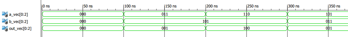
Figure 6. ISE simulation of the circuit shown in Figure 5.
Interpreting Std_Logic_Vector Data
There is one important point which needs further attention: As shown in the above example, the “std_logic_vector” data type is a way to represent a group of signals or a data bus. It is simply a string of ones and zeros, and there is no other interpretation for this string of ones and zeros. In other words, if we assign “011” to a_vec, this doesn’t mean that a_vec is equal to 3 (the decimal equivalent of “011”).
We cannot assume a weight for the different bit positions of a “std_logic_vector” signal. However, we can use type conversion functions and type casting to interpret the string of ones and zeros in a given “std_logic_vector” signal as a number. Type conversion will be discussed in a future article.
Ascending or Descending Index Range?
So far, we have used the “std_logic_vector” data type when defining input/output ports. Similarly, we can define a signal of “std_logic_vector” type. As an example, consider the following lines of code:
signal a: std_logic_vector(0 to 3);
...
a <= “0010”
Here, the first line defines a as a signal of type “std_logic_vector”. The index ranges from 0 to 3. Then, “0010” is assigned to a. With this assignment, as shown in Figure 7, we will have a(0)=0, a(1)=0, a(2)=1, and a(3)=0.
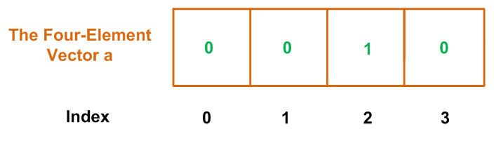
Figure 7.
The indexing style of this vector, which uses the keyword “to”, is called ascending. We can also use the keyword “downto” (instead of “to”) when we want a descending index range:
signal a: std_logic_vector(3 downto 0);
...
a <= “0010”
In this case, as shown in Figure 8, we’ll have a(3)=0, a(2)=0, a(1)=1, and a(0)=0.
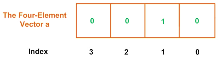
Figure 8.
The choice between ascending and descending order is often a question of the designer’s preferences, though it may be addressed by coding guidelines adopted by a particular organization. The most important thing is to choose one style and then follow it consistently; mixing the two different styles in one project can easily lead to trouble.
For example, consider the truth table for a 4-to-2 priority encoder, as given below. With a priority encoder, we generally consider the leftmost bit of the input vector to have the highest priority. For example, in the following truth table, when the leftmost input bit, x(3), is high, we don’t care about the state of the other three input bits and assert the outputs y and v, i.e., y=“11” and v=‘1’.
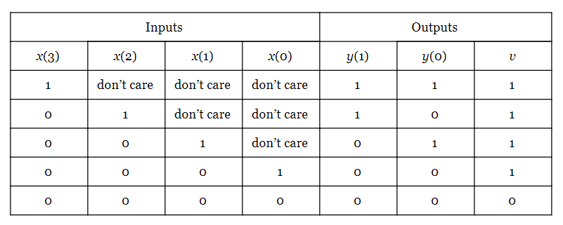
We observe that this truth table assumes the input vector x to have a descending index range because the element with the highest index is placed in the leftmost position. Now, assume that despite choosing a descending index range in the truth table, we use an ascending index range when declaring the input vector x and assign “0001” to x. In other words, we have:
signal x: std_logic_vector(0 to 3);
...
x <= “0001”
Since the rightmost bit of x is high, considering the general definition for a priority encoder, we expect the outputs y and v to be “00” and ‘1’, respectively. However, with the above code x(3) is high and, based on the above truth table, the output will be y=“11” and v=‘1’. To avoid such problems, we should use a descending index range consistently throughout the code.
Summary
- The “std_logic_vector” data type allows us to have code that is much more compact and readable. This data type provides us with a way to represent a group of signals or a data bus.
- We cannot assume a weight for the different bit positions of a “std_logic_vector” signal. However, we can use type conversion functions and type casting to interpret the string of ones and zeros in a given “std_logic_vector” signal as a number.
- The index range used in a “std_logic_vector” declaration can be either ascending or descending. The former uses the keyword “to”, and the latter uses the keyword “downto”.
- The choice between ascending and descending order is often a question of style, but it is important to apply this choice consistently throughout a particular project.
To see a complete list of my articles, please visit this page.
Featured image courtesy of Altera.