 Facebook
 Google
 GitHub
 Linkedin
Concurrent Conditional and Selected Signal Assignment in VHDL
This article will review the concurrent signal assignment statements in VHDL.
This article will review the concurrent signal assignment statements in VHDL.
This article will first review the concept of concurrency in hardware description languages. Then, it will discuss two concurrent signal assignment statements in VHDL: the selected signal assignment and the conditional signal assignment. After giving some examples, we will briefly compare these two types of signal assignment statements.
Please see my article introducing the concept of VHDL if you're not familiar with it.
Concurrent vs. Sequential Statements
To understand the difference between the concurrent statements and the sequential ones, let’s consider a simple combinational circuit as shown in Figure 1.
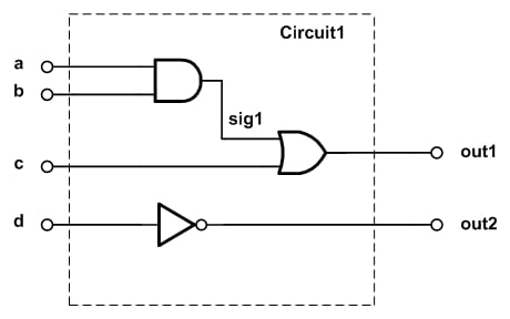
Figure 1. A combinational circuit.
If we consider the operation of the three logic gates of this figure, we observe that each gate processes its current input(s) in an independent manner from other gates. These physical components are operating simultaneously. The moment they are powered, they will “concurrently” fulfill their functionality. Note that while, in practice, the AND gate has a delay to produce a valid output, this does not mean that the OR gate will stop its functionality and wait until the output of the AND gate is produced. The OR gate will function all the time; however, its output will not be valid until its inputs have settled.
Now, let’s examine the VHDL description of Figure 1. This is shown below:
library IEEE;
use IEEE.STD_LOGIC_1164.ALL;


entity comb1 is
    Port ( a : in  STD_LOGIC;
           b : in  STD_LOGIC;
           c : in  STD_LOGIC;
           d : in  STD_LOGIC;
           out1 : out  STD_LOGIC;
           out2 : out  STD_LOGIC);
end comb1;

architecture Behavioral of comb1 is
	signal sig1: std_logic;
begin
	sig1 <= ( a and b );
	out1 <= ( sig1 or c );
	out2 <= (not d);

end Behavioral;
The main part that we are here interested in is the definition of the three gates:
sig1 <= ( a and b );
out1 <= ( sig1 or c );
out2 <= (not d);
Each of these lines describes a physical component in Figure 1. For example, the second line, which describes the OR gate, takes sig1 and c as inputs and produces the OR of these two values. We saw that the physical components of Figure 1 operate concurrently. Hence, it is reasonable to expect that the VHDL description of these gates should be evaluated in a concurrent manner. In other words, the above three lines of the code are executed at the same time and there is no significance to the order of these statements. As a result, we can rewrite the architecture section of the above code as below:
architecture Behavioral of comb1 is
	signal sig1: std_logic;
begin

	out1 <= ( sig1 or c );
	out2 <= (not d);
	sig1 <= ( a and b );

end Behavioral;
Since these statements are evaluated at the same time, we call them concurrent statements. This type of code is quite different from what we have learned in basic computer programming where the lines of code are executed one after the other. For example, consider the following MATLAB code:
clear all;
a=1;
b=0;
c=1;
d=0;
sig1=and(a, b);
out1=or(sig1, c)
out2=not(d)
This code produces out1=1 and out2=1. However, if we change the order of the statements to the following, the program will stop working because we are trying to use sig1 before it is generated.
out1=or(sig1, c)
out2=not(d)
sig1=and(a, b);
While the VHDL code describing Figure 1 was executed concurrently, the above MATLAB code is evaluated sequentially (i.e., one line after the other). VHDL supports both the concurrent statements and the sequential ones. It's clear that the concurrent VHDL statements will allow us to easily describe a circuit such as the one in Figure 1 above. In a future article, we'll see that the sequential VHDL statements allow us to have a safer description of sequential circuits. Furthermore, using the sequential VHDL, we can easily describe a digital circuit in a behavioral manner. This capability can significantly facilitate digital hardware design.
The following figure illustrates the difference between concurrent and sequential statements.
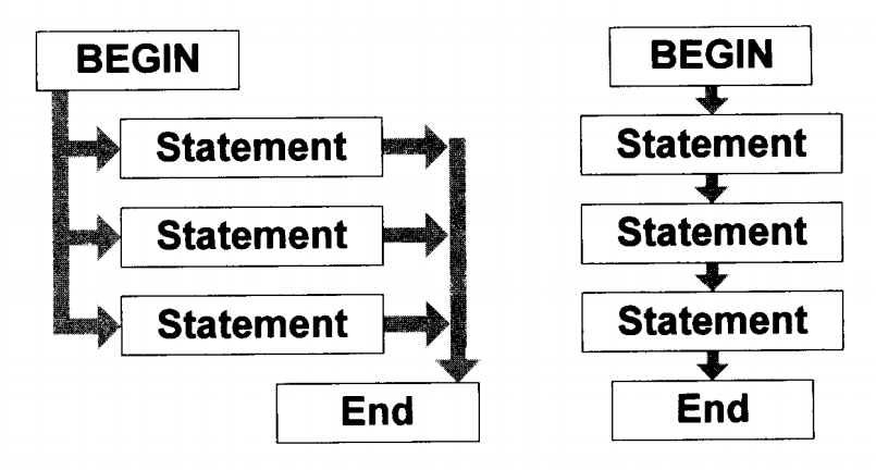
Figure 2. The difference between concurrent and sequential statements. Image courtesy of VHDL Made Easy.
Now let's take a look at two concurrent signal assignment statements in VHDL: “the selected signal assignment statement” and “the conditional signal assignment statement”.
Selected Signal Assignment or the “With/Select” Statement
Consider an n-to-one multiplexer as shown in Figure 3. This block should choose one out of its n inputs and transfer the value of this input to the output terminal, i.e., output_signal.
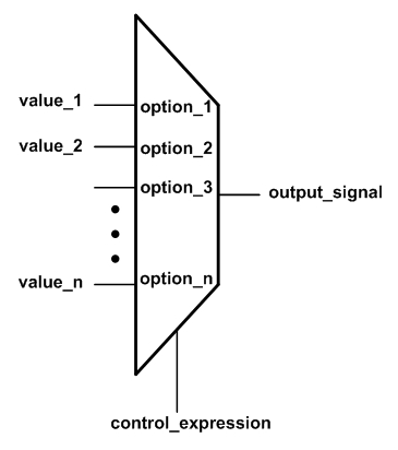
Figure 3. A multiplexer selects one of its n inputs based on the value of the control_expression.
The selected signal assignment allows us to implement the functionality of a multiplexer. For example, the VHDL code describing the multiplexer of Figure 3 will be
with control_expression select
	output_signal <= value_1	when	option_1,
	 	         value_2	when	option_2,
                         ...
                         value_n	when	option_n;
Here, the value of the control_expression will be compared with the n possible options, i.e., option_1, option_2, …, option_n. When a match is found, the value corresponding to that particular option will be assigned to the output signal, i.e., output_signal. For example, if control_expression is the same as option_2, then value_2 will be assigned to the output_signal.
Note that the options of a “with/select” assignment must be mutually exclusive, i.e., one option cannot be used more than once. Moreover, all the possible values of the control_expression must be included in the set of the options. The following example clarifies these points.
Example 1: Use the "with/select" statement to describe a one-bit 4-to-1 multiplexer. Assume that the inputs to be selected are a, b, c, and d. And, a two-bit signal, sel, is used to choose the desired input and assign it to out1.
The code for this multiplexer is given below:
library IEEE;
use IEEE.STD_LOGIC_1164.ALL;

entity Mux1 is
    Port ( a : in  STD_LOGIC;
           b : in  STD_LOGIC;
           c : in  STD_LOGIC;
           d : in  STD_LOGIC;
           sel : in  STD_LOGIC_VECTOR (1 downto 0);
           out1 : out  STD_LOGIC);
end Mux1;

architecture Behavioral of Mux1 is

begin
	with sel select
			out1 <= a when "00",
				  b when "01",
				  c when "10",
				  d when others;

end Behavioral;
Note that since the std_logic data type can take values other than “0” and “1”, the last line of the “with/select” statement needs to use the keyword “others” to take all the possible values of sel into account.
The following figure shows the simulation of this code using the Xilinx ISE simulator. (In case you’re not familiar with ISE, see this tutorial.) As shown in this figure, from 0 nanosecond (ns) until 300 ns the select input, sel, is 00, and, hence, out1 follows the input a. Similarly, you can verify the intended operation for the rest of the simulation interval.
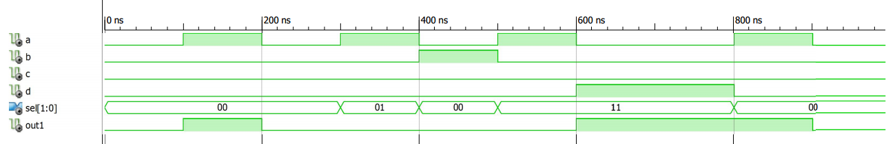
Figure 4. The ISE simulation for the multiplexer of Example 1.
Example 2: Use the “with/select” statement to describe a 4-to-2 priority encoder with the truth table shown below.
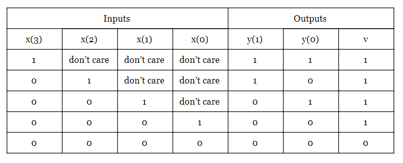
The following VHDL code can be used to describe the above truth table:
library IEEE;
use IEEE.STD_LOGIC_1164.ALL;


entity prio_encoder1 is
    Port ( x : in  STD_LOGIC_Vector(3 downto 0);
           y : out  STD_LOGIC_Vector(1 downto 0);
           v : out  STD_LOGIC);
end prio_encoder1;

architecture Behavioral of prio_encoder1 is

begin
	with x select
		y <= "11" when "1000" | "1001" | "1010" | "1011" | "1100" | "1101" | "1110" | "1111",
		         "10" when "0100" | "0101" | "0110" | "0111",
		          "01" when "0010" | "0011",
		          "00" when others;
                v <= ( x(3) or x(2) or x(1) or x(0) );

end Behavioral;
The ISE simulation is shown in Figure 5.
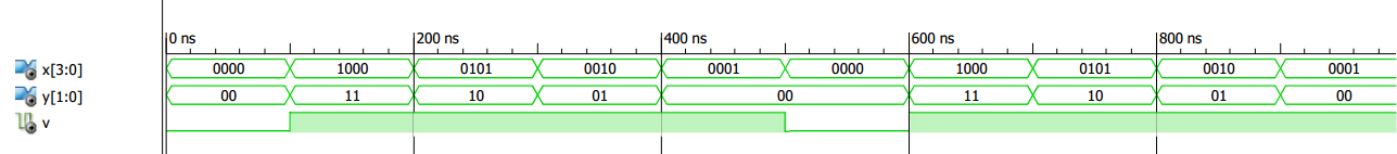
Figure 5. The ISE simulation for the priority encoder of Example 2.
Conditional Signal Assignment or the “When/Else” Statement
The “when/else” statement is another way to describe the concurrent signal assignments similar to those in Examples 1 and 2. Since the syntax of this type of signal assignment is quite descriptive, let’s first see the VHDL code of a one-bit 4-to-1 multiplexer using the “when/else” statement and then discuss some details.
Example 3: Use the when/else statement to describe a one-bit 4-to-1 multiplexer. Assume that the inputs to be selected are a, b, c, and d. And, a two-bit signal, sel, is used to choose the desired input and assign it to out1.
The code will be
library IEEE;
use IEEE.STD_LOGIC_1164.ALL;

entity Mux2 is
    Port ( a : in  STD_LOGIC;
           b : in  STD_LOGIC;
           c : in  STD_LOGIC;
           d : in  STD_LOGIC;
			  sel : in  STD_LOGIC_VECTOR (1 downto 0);
           out1 : out  STD_LOGIC);
end Mux2;

architecture Behavioral of Mux2 is

begin
	out1 <= a when sel="00" else
		 b when sel="01" else
		 c when sel="10" else
		 d;

end Behavioral;
In this case, the expressions after “when” are evaluated successively until a true expression is found. The assignment corresponding to this true expression will be performed. If none of these expressions are true, the last assignment will be executed. In general, the syntax of the “when/else” statement will be:
output_signal <= value_1	when	expression_1 else
      value_2	when	expression_2 else
      ...
      value_n;
We should emphasize that the expressions after the “when” clauses are evaluated successively. As a result, the expressions evaluated earlier has a higher priority compared to the next ones. Considering this, we can obtain the conceptual diagram of this assignment as shown in Figure 6. This figure illustrates a conditional signal assignment with three “when” clauses.
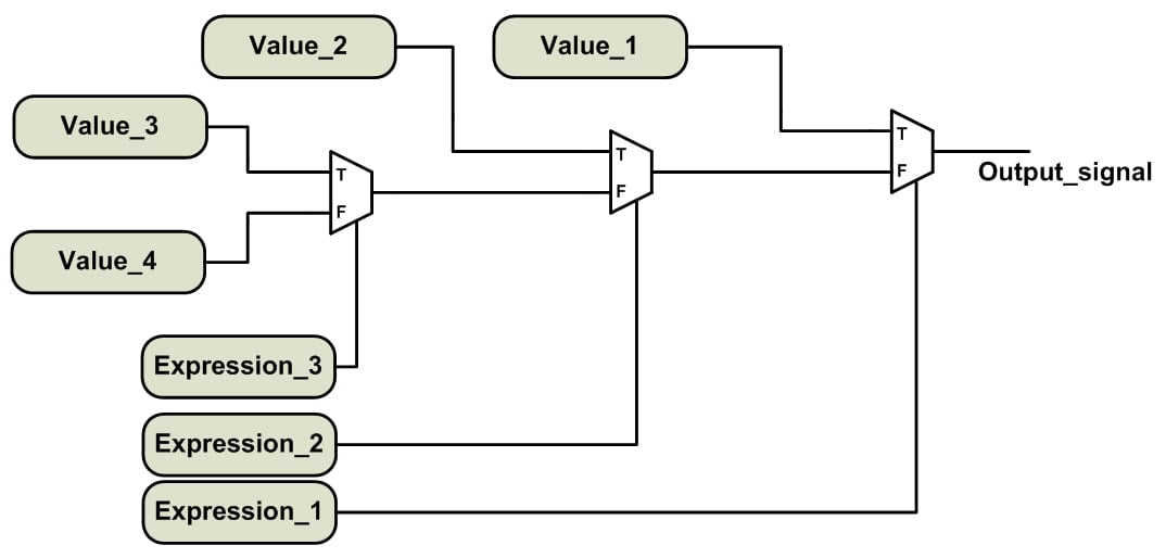
Figure 6. The conceptual implementation of a “when/else” statement with three “when” clauses.
Let’s review the main features of the selected signal assignment and the conditional signal assignment.
“With/Select” vs. “When/Else” Assignment
As mentioned above, the options of a “with/select” assignment must be mutually exclusive, i.e., one option cannot be used more than once. Moreover, all the possible values of the control_expression must be included in the set of options. While the “with/select” assignment has a common controlling expression, a “when/else” assignment can operate on expressions with different arguments. For example, consider the following lines of code:
out1 <= ‘0’ when reset1=’0’ else
	 d  when clk=’1’;
In this case, the expressions are evaluating two different signals, i.e., reset1 and clk.
For the “when/else” assignment, we may or may not include all the possible values of the expressions to be evaluated. For example, the multiplexer of Example 3 covers all the possible values of sel; however, the above code does not. The above code implies that out1 should retain its previous value when none of the expressions are true. This causes the inference of a latch in the synthesized circuit.
Another important difference between the “with/select” and “when/else” assignment can be seen by comparing the conceptual implementation of these two statements. The priority network of Figure 6 involves a cascade of several logic gates. However, the “with/select” assignment avoids this chain structure and has a balanced structure. As a result, in theory, the “with/select” statement may have better performance in terms of the delay and area (see RTL Hardware Design Using VHDL: Coding for Efficiency, Portability, and Scalability, Xilinx HDL Coding Hints, and Guide to HDL Coding Styles for Synthesis).
In practice, we generally don’t see this difference because many synthesis software packages, such as the Xilinx XST, try not to infer a priority encoded logic. Though we can use the PRIORITY_EXTRACT constraint of XST to force priority encoder inference, Xilinx strongly suggests that we use this constraint on a signal-by-signal basis; otherwise, the constraint may guide us towards sub-optimal results. For more details see page 79 of the XST user guide.
Summary
- Concurrent statements are executed at the same time and there is no significance to the order of these statements. This type of code is quite different from what we have learned in basic computer programming where the lines of code are executed one after the other.
- The selected signal assignment or the "with/select" assignment allows us to implement the functionality of a multiplexer.
- The options of a “with/select” assignment must be mutually exclusive, i.e., one option cannot be used more than once. Moreover, all the possible values of the control_expression must be included in the set of the options.
- For the "when/else" statement, the expressions after the “when” clauses are evaluated successively. As a result, the expressions evaluated earlier has a higher priority compared to the next ones.
- One important difference between the “with/select” and “when/else” assignment can be seen by comparing the conceptual implementation of these two statements. The "when/else" statement has a priority network; however, the “with/select” assignment avoids this chain structure and has a balanced structure.
To see a complete list of my articles, please visit this page.
Featured image used courtesy of Parallella.


awesome
Great content. The link to the ISE guide requires password. Can we get that posted again? Thanks!