Facebook
 Google
 GitHub
 Linkedin
Analog to Digital Conversion
Video Lectures created by Tim Feiegenbaum at North Seattle Community College.
We are continuing in 15-4 and in this section, we're looking at analog to digital conversion. In the previous section, we looked at digital to analog. Now, we're going to be looking at the process of taking an analog input and converting it to a digital representation. Here we would have our analog input and then on A or C, B, and A over here we would have our digital output.
An analog to digital is the functional opposite of a digital to analog converter. An analog voltage or current is applied to the ADC input and is transformed into an equivalent digital value. Now, this particular circuit is called a flash analog to digital converter.
Let's talk a little bit about this circuit. We've already mentioned that we have an analog value coming in and our goal is to convert it to a digital output. Now, this is a mighty three-bit converter. Usually, you would have converters that are much larger than that, maybe 16, 24 or whatever. This is again ... we're introducing the subject and we want to keep it basic.
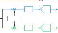
Here we have the overall process, analog to digital and so what we're going to do is start out with 24 volts and we're going to put it across a zener diode here which will regulate to 10 volts. That 10 volts will be spread out across these components. Now I noticed it says R. It doesn't give you a value of R but all of the R's are the same value. That 10 volt is going to be distributed in series across these eight components. If we took ten divided by eight we would have 1.25, so that would be 1.25 volt increments across these components. If you'll notice here ... down here this is ground then we start at 1.25, we add 1.25 to 2.5, add 1.25 to 3.75 and so on, up to 8.75 and then there are 10 volts right here.
Now notice that these voltages, a reference from each of these is fed over to A and this is a comparator. This is an op-amp comparator and what these comparators will do is that if the input voltage exceeds this reference value, we'll get a high out of these comparators. If the voltage is less than that reference value, we'll get a low. Then those values will be fed into the logic over here and this logic circuit will take that value and convert it to its binary equivalent.
Let's start out with a ... let's pretend we have an analog voltage coming in here and we'll say it's 2 volts. It's going to come in and 2 volts is right about here. Remember that two volts are coming in on this lean so it is equally applied to every comparator. Now that 2 volts are going to be greater than this 1.25 so it will put out a one here. This is 2.5-volt reference coming in right here; it is less than that so this will be a zero. What will occur, there will be lows on all of these outputs. There will be a high only on this one.
Let's see how this affects this logic. First of all, we have C over here and so we would have the low coming in here and we'll go over here so this would be a low. We're dealing with three-bit logic, we're going to have three possible bits; the most significant bit is going to be a zero.
Then let's keep going. Here, we have several inputs coming in here. We have a zero coming in here; we have a zero here, which will be inverted to a high, and then we have a low coming in here, so a one and a zero going to this AND gate will produce a zero, and then a zero and zero going into this OR gate will produce a zero. Our second most significant bit B is also going to be a zero.
Then we come down here to the last set of bits here. Let's see, we have the zero coming in right here. Notice these are exclusive ORs and then we have a zero coming in here. We have a zero coming into this gate and coming into this gate, again a zero. Coming in from ... let's see what gate is this one that is connected here. Most of these are zeros and then coming in here from ... we have a zero here and last but not the least, we finally have a one.
Now remember, exclusive OR, they only put out an output when the input is either a zero and a one or a one on a zero. It's because with a zero and zero or one on one there is no output, so in this gate, we have a zero on a zero that will give us a zero. Then we have a zero on a zero coming in here, a zero. Zero on a zero here produces zero. Zero on one here produces a one. Does zero on one here ... now, these are two different ... so they'll produce a one and then the zero on the one here, this would produce our one.
Here we would have our logic level of one. Now that is if we had a two-volt input. Now, let's do another one. This time let's put in a ... Let's see, and take note here. Remember this is a three-bit converter and so with three bits there are eight possible states and that's including zero. Note that there are one, two, three, four, five, six, seven op-amps, so every possible value must have an op-amp representation in this type of circuit.
Let's put in another value. Let's go in, let's say we have an input value of 5.1 volts and we'll send that in here. That's going to be slightly greater than 5 so that we have one, two, three, four. What we would expect is a binary four. Now, what I'm going to do I'm going to change the pen color here just so we can separate out what we're ... Let's just make it black. Now, we're going to go in here. We're going to put in an analog value of 5.1 volts so that will ... this comparator will go high. We'll put a one here, in fact, all of these below will be high. Put ones on all these and then these above here will all be zero.
Given the fact that it's 5.1, the value should be one, zero, zero. Let's see what we get when we do the evaluation. We're going to put a one here which will feed over here to C and there and that in fact corresponds to our one right there. Let's see what happens to B and C. Coming in here, let's see. We're going to come into this OR gate. That would be a one there. Let's see, we have come into one there and then from here again, we had a zero. That were inverted to a one and then from down here, now we have a one coming in here. Let's see, we do have a one coming in here and we had a ... excuse me, there is the problem. At five, actually this is not a zero; this is a one right here, so we have a one coming that is going to make this a zero. Zero and a one will give us the zero and let's see. Did we actually have a ... coming in here...? Wait a minute, what do we have coming in here? This should be a zero. Did I call it a one? Yes, because that is coming on from here. Wait a minute; let's see what have we got. Coming in, this is a zero. Evaluate, zero on one, zero. Zero on zero going into the OR again here and we have a zero and you've got to really watch yourself when you do these; too many values.
Okay. The next one, last bit. We would have a zero here and on this input, we would have a zero and coming in from here, we have another zero. Coming in from here ... now this ... right here we're going to have a one and coming in here we're going to have a one. From here there will be a one and from here there'll be a one, so let's evaluate.
Okay. A zero on a zero, we're going to have a zero here and a zero and a zero here. This will make a zero and then we have a one and a one coming out of here but that is going to be again a one and a one is a zero. A one and a one, that is a zero. A zero and zero make a zero. It looks like a zero-zero makes a zero and a zero, zero, zero. We have all zeros. This gets really confusing very quickly but you can see that when we put that 5.1 volts that will equate to a binary one, zero, zero which is what we would expect.
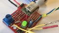
Now, this next picture here, this is the actual circuit that we just looked at; this is from multi-sim, and I encourage you to go there and actually use this circuit which you'll be able to do. You'll know up here there is a variable component and you can press the letter "A" and it will change the value of this component. What this does ... notice this is the voltage that has been applied as the analog value that we're evaluating, so you can set this to any of those analog values between zero and ten. You should be able to illuminate the light bulbs that are attached to the three logic levels indicating the three bits of our possible outputs. A will ... I think A makes it goes down and then if you press the shift key and A will make this value go up. What I have done, I went in and I set this value to just over 5 volts which would be right here. This would equate to the binary 100 that we looked at on the previous screen. You can see here, we have a one, zero, and a zero indicating that binary four.
Well, this has been a quick introduction to the whole concept of analog to digital conversion. As I mentioned earlier these circuits can get quite complex due to their sizes and this is only a three-bit converter and these will often be much higher bit ratios. This is just one way of doing analog to digital conversion.
There are other methods.
Related Content