 Facebook
 Google
 GitHub
 Linkedin
LED Chaser… With a Twist!
Build an LED chaser with a little twist: we'll be using a microcontroller and an LCD along with the usual 4017 counters.
Get illuminating with an MCU and an LCD along with 4017 counters.
Requirements
- Computer with MPLAB X and the XC8 compiler
- PICKit 3 or equivalent device to program the microcontroller
- PIC16F877A
- Ribbon cables, pin headers, 16x2 LCD and push switches
- Breadboards and jumper wires, if you want to breadboard
- Parts from parts list
Introduction
The internet is overfilling with LED chasers, Knight Riders, and different ways to blink a series of LEDs in a certain pattern. In this article, I'm going to make yet another LED chaser, or a Knight Rider, but this one is with a little twist: we'll make an LCD with a menu that will allow you to choose different patterns and speeds.
This project has five PCBs: four PCBs with LEDs and one with a microcontroller. On the LED's PCB, there are two ICs: the HCF4017BE Johnson counter. The counter has one clock input pin and 10 output pins. For each high pulse received on the clock pin, the next output pin is set high, starting with output pin 0. Read more about the IC in the link.
The last PCB has a PIC16F877A microcontroller. To this microcontroller I've connected a few switches, a potentiometer, and an LCD. The microcontroller clock on each counter IC is in a different order. The microcontroller can also reset the counter ICs. In the software, there's a menu that allows you to choose between some predefined patterns. You navigate with one of the switches and enter the menu choice with another. The third switch is the reset switch. One of the patterns lets you use the potentiometer to change the speed for the "running" LEDs. This is done with the microcontroller's built-in ADC module. ADC will not be discussed in this article.
Hardware
In order to let the LEDs "run" back and forth, I used two 4017s for each 8 LEDs. On the first 4017 IC, I connected Q1 to LED one, Q2 to LED two and so on. The output on the second 4017 IC is connected in the opposite direction. Q1 to LED eight, Q2 to LED seven, etc.... I made four PCBs based on this schematic:

Click on image for full resolution.
Then I made one PCB from this schematic:
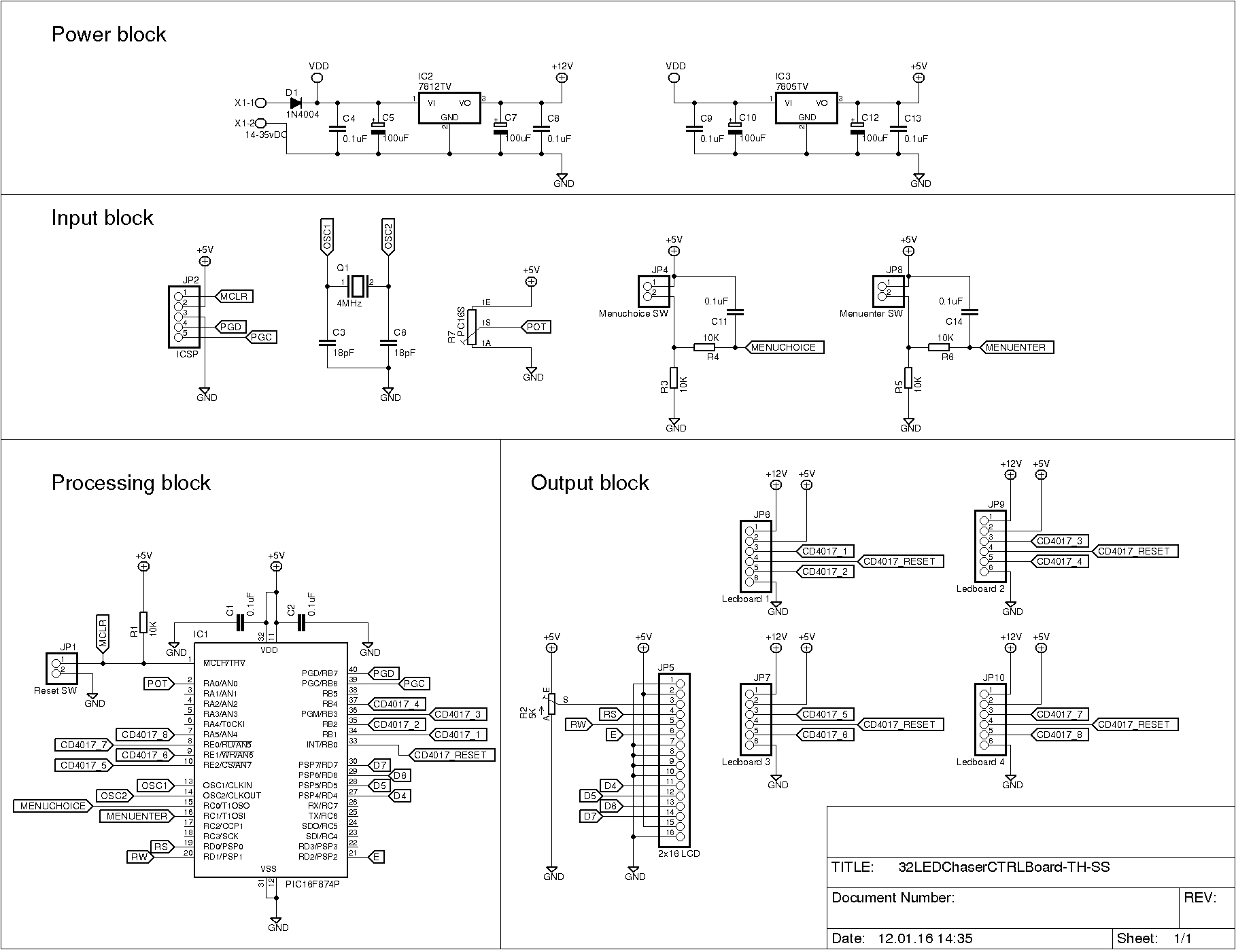
Click on image for full resolution.
To save space, I used some SMD components. The capacitors on the microcontroller's crystal are 0603 sized. I've never soldered anything that tiny, and I was surprised how easy it was. I just need a little practice. The other SMD components are 0805 sized, apart from the obvious throughhole ones.
Parts List
Here's an edited part list generated by EagleCAD. Remember you need to multiply the LED PCB by four.

Software
I'm using Microchip's library for the LCD. All the source code files are copied into one large lcd.c file, and the lcd.h file is edited to match my connections. The menu is built up using two switch-case loops. The first loop updates the LCD with appropriate text, and assigns a value to a variable (MenuItem). When the MENUENTER switch is pressed, the value in MenuItem is passed on to the next switch-case loop, which executes the desired option.
The 4017 has a clock pin and a reset pin. All the 4017s clock pins are connected to different pins on the microcotroller. All the reset pins are tied together and connected to one pin on the microcontroller. With this configuration I can clock individual 4017 ICs. Since all the reset pins are tied to one pin on the microcontroller, I only have to pulse that pin high to reset all 4017 ICs.
Navigating through the menu, is done with a push button. To you, one push might look like one push, but to the microcontroller there's a different story. The switch will bounce, causing the microcontroller to think that you are pushing the button many times, which is called switch bouncing. Read more about this here: Switch Bounce and How to Deal with It. I'm dealing with this in the software.
You have 14 different patterns in the software. This is the string that makes the menu options:
// MENUOPTION STRINGS
char prg1[] = "RUN 1. 4017     "; // Clocks the first CD4017
char prg2[] = "RUN 2. 4017     "; // Clocks the second CD4017
char prg3[] = "RUN 3. 4017     "; // ... and so on ...
char prg4[] = "RUN 4. 4017     ";
char prg5[] = "RUN 5. 4017     ";
char prg6[] = "RUN 6. 4017     ";
char prg7[] = "RUN 7. 4017     ";
char prg8[] = "RUN 8. 4017     ";
char prg9[] = "UP - DOWN       "; // LEDs "run" up and down endlessly
char prg10[] = "USER SPEED     "; // User set the speed
char prg11[] = "RUN ODD        "; // Clock only ODD number CD4017 -> 1, 3, 5, 7
char prg12[] = "RUN EVEN       "; // Clock only EVEN number CD4017 -> 2, 4, 6, 8
char prg13[] = "RUN EVEN - ODD "; // Clock first EVEN numbers then ODD numbers -> 2, 4, 6, 8, 7, 5, 3, 1
char prg14[] = "RUN ODD - EVEN "; // Clock firs ODD numbers then EVEN numbers -> 7, 5, 3, 1, 2, 4, 6, 8
The software is fairly well commented, so no further discussion will be made. You can download the source code in the link below.
jc_pic16f877a-32ledchaser.c.zip
Conclusion
In this article I've made yet another LED chaser for the internet, but the little twist here is the LCD with a menu. A total of 32 LEDs are running up and down, or in different patterns. The microcontroller has some unused pins, which means that you can add even more PCBs with LEDs. Are you up for it?
Pictures and Video
SOT-23 transistor and a 0805-resistor:
![]()
I made four of these boards:

This is the controllerboard:


16 x 2 LCD:

Give this project a try for yourself! Get the BOM.


Great article, I really enjoyed reading it. Quick note, of the parts list you state you are using the 16F877A but on the schematic the part is identified as 16F874P. Just thought you’d like to know 😊