 Facebook
 Google
 GitHub
 Linkedin
Build a 2-Digit Up/Down Counter with a PICAXE 20M2
Counters using 7-segment LEDs are fun and useful projects for scoreboards and other numerical displays; here's one you can build.
Counters using 7-segment LEDs are fun and useful projects for scoreboards and other numerical displays; here's one you can build.
Background
The project in this article makes use of a PICAXE 20M2 microcontroller. If you are familiar with this family of µc's, jump right in, but if you need a little background info or refresher training, you can find a series of PICAXE articles (including tutorials) here.
Introduction
Display counters are popular for experimentation as well as for practical projects such as scoreboards and "now serving" displays. This article details a two-digit up/down counter that is inexpensive and relatively simple, yet provides an introduction to hardware and software techniques that are applicable to more full-featured displays. A PICAXE 20M2 microcontroller provides the "horsepower" to control a pair of common cathode seven-segment LEDs. Two tactile pushbuttons provide for the human interface.
The display assembly is built on perfboard and the rest of the circuit is built on a solderless breadboard. The power supply can be any well-filtered, regulated 5VDC supply; construction details for the regulator shown are provided here. The photo below shows the entire project.

The Schematic Diagram
The circuit schematic is shown below. Note that the component designations and wire colors in the breadboard photo above agree with those in the schematic diagram below.

The LED assembly inside the red box in the schematic diagram is a separate subassembly connected to the solderless breadboard via nine wires: one wire for each of the seven segments in the display, and one each for the cathode connection in the two digits. Each of the seven segments of the display is equipped with a current limiting resistor (R3 through R10.) Note that the decimal point is provided with a resistor (R7) but the decimal point is not used in this project, so the resistor can be omitted if desired.
The remainder of the electrical design is intentionally simple in order to reduce parts count and cost. J1, R1, and R2 make up the standard PICAXE programming circuit. SW1, SW2, R12, and R13 form the man-machine interface that is used to instruct the PICAXE whether to increment or decrement the count.
Q1, Q2, and R11 switch the ground on and off to the cathode of the two displays. As pinB.7 of the PICAXE is toggled, one digit is turned off and the other is turned on. This toggling action is done very rapidly, and through a phenomenon called "POV" (Persistence of Vision,) both displays appear to be lit simultaneously. As you see, the transistors used are N-channel MOSFETS, but at the cost of one additional resistor, NPN bipolar junction transistors could be used as shown below.

The PICAXE 20M2 is rated as able to source up to 25mA per output pin, however it is only rated to be able to source a total of 80mA. In order to stay within that rather stringent requirement, the current to each LED segment is limited to less than 10 mA by the 360 ohm resistors. (Remember that only one display at a time is lit due to the toggling action of pinB.7.) As a result, the display is not as bright as desired, but is sufficient for experimentation purposes. To avoid this deficiency, you could add a simple driver transistor circuit to each segment of the display.
Parts Required
| Reference No. | Description | Qty. | Source | Part Number |
|---|---|---|---|---|
| J1 | Jack, 3.5mm, 3 Conductor | 1 | Digi-Key | CP1-3533NG-ND |
| R1 | Resistor, .25W, 22kOhms | 1 | Digi-Key | 22KQBK-ND |
| R2, R12, R13 | Resistor, .25W, 10kOhms | 3 | Digi-Key | 10KQBK-ND |
| R3-R10 | Resistor, .25W, 360Ohms | 8 | Digi-Key | 360QBK-ND |
| R11 | Resistor, .25W, 100kOhms | 1 | Digi-Key | 100KQBK-ND |
| C1 | Capacitor, Ceramic, 50V, .1uF | 1 | Digi-Key | BC2665CT-ND |
| SW1, SW2 | Switch, Pushbutton, Tactile, NO | 2 | Digi-Key | 450-1650-ND |
| Q1, Q2 | Transistor, MOSFET, N-channel, BS170 | 2 | Jameco | 256031 |
| U1 | Microcontroller, PICAXE, 20M2 | 1 | PHAnderson.com | PICAXE-20M2 |
| LED1, LED2 | Display, LED, 7-Segment, Common Cathode, Red | 2 | on-line | LTS-6780R (can substitute similar part) |
| N/A | Cable, PICAXE, Programming, USB | 1 | PHAnderson.com | AXE027 |
| N/A | Breadboard, Solderless, 400 Position | 1 | Digi-Key | 377-2094-ND |
| N/A | Wire, Solid, AWG22, Assorted Colors | 1 | Jameco | 2153705 |
| N/A | Perfboard, Datak, 12-602B | 1 | on-line | 12-602B (can substitute similar part) |
Assembly
Building the breadboard is easy; just follow the schematic diagram and/or the photograph previously presented.
Construction of the LED assembly is not complex, but it does require an understanding of the 7-segment LEDs being used. The assembly pictured above uses two LTS6780R displays, one of which is depicted below. The numbers 1-10 denote the connecting pins protruding from the rear of the display; pin 7 connects to the anode of the A segment on the display, pin 6 connects to the anode of the B segment, and so on. Pins 3 and 8 both connect to the cathode of all the segments, hence the description "common cathode" to refer to displays that use this arrangement. (In case you don't remember, the positive voltage is connected to the anode, and "ground" is connected to the cathode in order to light an LED. Of course, a suitable current limiting resistor must be used with each segment to avoid damage to the LED.)

This project uses two LTS6780R displays with like-lettered segments wired in parallel, i.e., the A segment in one display is wired in parallel with the A segment in the other display, the B with the B, etc. Note that the cathode pins are not wired in parallel.
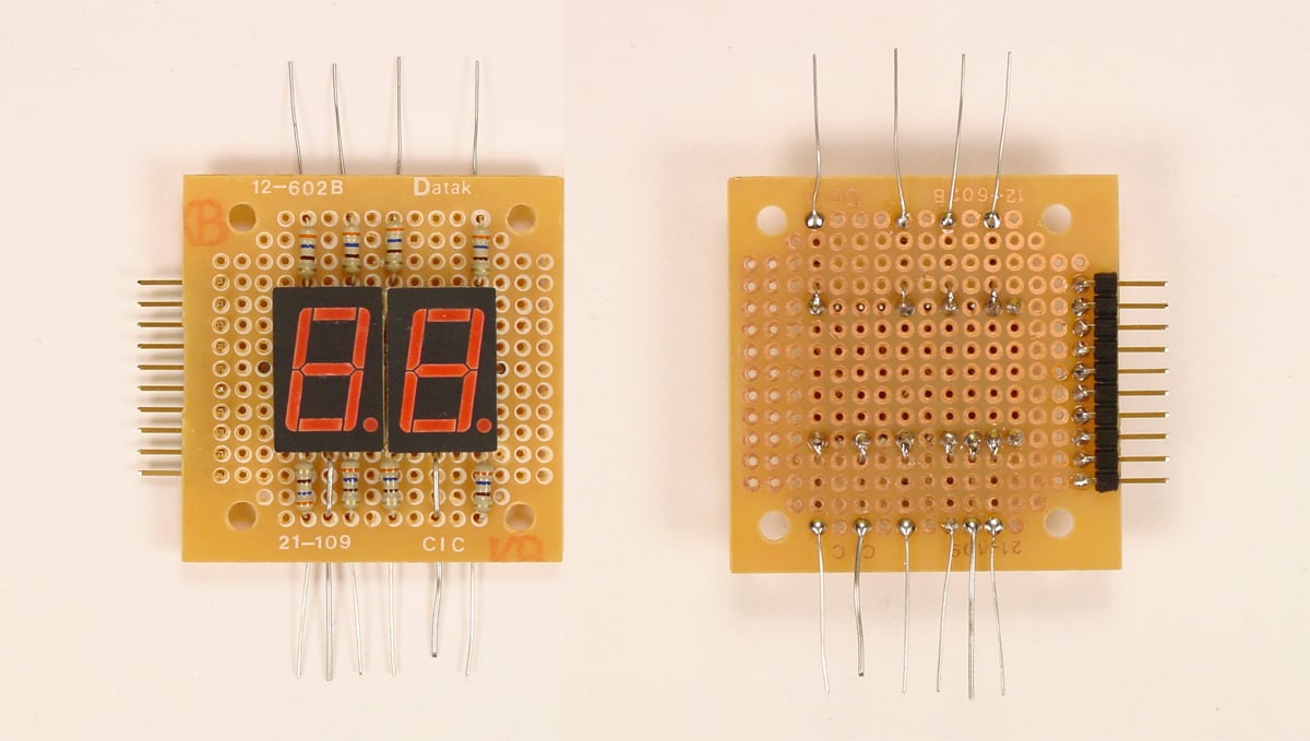
Physically, the two displays are arranged side-by-side and wired together as shown in the rear view below. Notice that the tens digit is on the right in the photo and the ones digit is on the left. See the schematic diagram for a graphic representation of this wiring scheme.

Once wired as shown above, the two-digit subassembly is mounted on a perfboard and wired as shown in the photos below. For clarity, the top photo shows the wiring in progress and the bottom photo shows the wiring completed. Of course, you may use any physical arrangement you choose as long as the wiring is done per the schematic diagram shown.
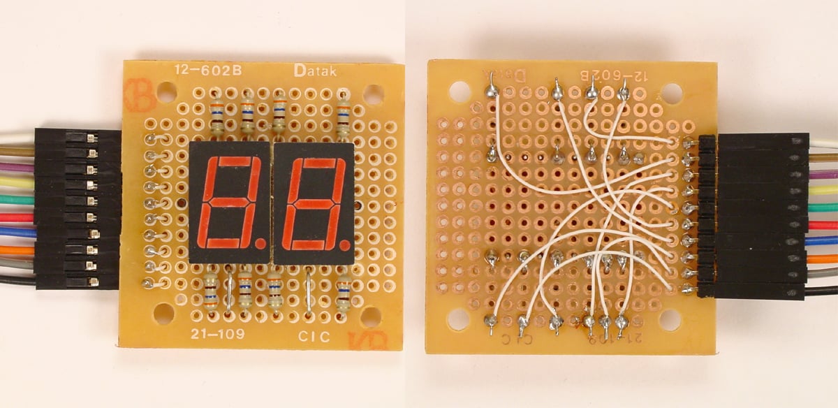
Although the use of connectors makes it more convenient to connect the LED assembly to the solderless breadboard, they are not required. You can solder wires directly to the LED assembly, and plug the wires into the solderless breadboard. Note that the wire colors shown in the photograph directly above are no longer correct; follow the color code shown on the schematic and the overall project assembly photograph.
The Code
Like the hardware design, the code for this project was written with the goal of being easy to understand, implement, and modify. To that end, it is copiously commented, and will not be explained in detail in the text of this article. However, an overview and general discussion of the code's structure and operation will be presented. It is suggested that you download the code, open it in PICAXE Editor 6 (PE6), and follow along.
PICAXE-20M2_2-Digit_UpDown_Counter.zip
Lines 1 through 8 are comments that document the name and purpose of the code, and identify the associated schematic.
Lines 10 through 27 only run at startup or after a reset.
Lines 10 through 22 are setup lines to assign variables and set all of pinsB as outputs.
Lines 24 through 27 are used to set the display output at the count it was at the last shutdown. Note that the very first time the program is run, the display will be blank because no segment data will have been stored.
Lines 29 through 41 constitute the main part of the program. Lines 32 through 41 form a repetitive loop that runs continously until either the increment or decrement button is pushed. The LEDs are continuously updated. Note that the units digit is lit during lines 37 and 38 for 5 milliseconds and then goes out. The tens digit is lit during lines 39 and 40 for 5 milliseconds and then goes out. The cycle continues until either the increment or decrement button is pressed, which directs execution to either line 43 or line 63.
Lines 43 through 59 cause the count to be increased by 1 and stored, and the segment data for the units and tens digits to be called and stored.
Lines 63 through 79 cause the count to be decreased by 1 and stored, and the segment data for the units and tens digits to be called and stored.
Lines 85 through 88 constitute a subroutine, and allow the correct LED segments to be called for the units digit based on the count.
Lines 90 through 93 constitute a subroutine, and allow the correct LED segments to be called for the tens digit based on the count.
Lines 95 through 99 constitute a subroutine, and cause the tens digit to be blanked if the count is from 0 through 9.
Now What?
This project should provide you with a starting point for designing and writing code for your own project. It could be a full featured scoreboard for your favorite sport or something more exotic. At the very least, it should whet your appetite for bigger and better PICAXE projects. Have fun!
Give this project a try for yourself! Get the BOM.


Instead of buttons how would I wire up a POT to control the counter?
Hi,
Could you advise how I can tweak the code to include a separate input (from a pushbutton) to reset the counter to zero?
Any response much appreciated - thanks.
David M