Facebook
 Google
 GitHub
 Linkedin
The Isolated Half-Bridge: An IGBT Gate Driver Module with Current Sense
This project brief describes how to assemble an isolated half-bridge IGBT gate driver module built around the NCD57085DR2G. It features onboard current sensing and overcurrent protection.
The Isolated Half-Bridge with Current Sense is a compact power electronics module designed to drive two IGBTs in a half-bridge configuration. Each gate driver channel uses an NCD57085DR2G single-channel gate driver IC from onsemi, paired with an R12P21509D isolated DC-DC converter module that generates the +15 V / –9 V bias required for proper IGBT operation.
A shunt resistor in the IGBT emitter path provides current sensing for overload detection and current monitoring. Power LEDs on each channel indicate the presence of the gate driver supply voltage. Figure 1 shows the fully assembled module.
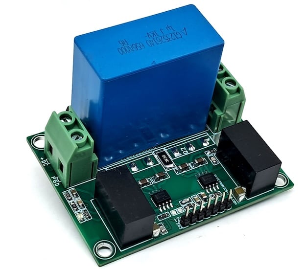
Figure 1. The fully assembled Isolated Half-Bridge with Current Sense module.
High-current screw terminals accommodate the load connection and DC bus input. A seven-pin header connector provides access to the high-side and low-side PWM inputs, fault output, and gate driver power. The PCB supports TO-247 package IGBTs, allowing users to select devices appropriate to their application.
Specs and Features
- Supply: 12–20 VDC
- DC-DC Converter (R12P21509D) Output: +15 V / –9 V
- Gate Driver (NCD57085DR2G) Peak Output Current: +7 A / –7 A
- IGBT (AFGHL40T65RQDN): 40 A, 650 V
- Maximum Load Voltage: 500 V DC
- Current Sense Threshold: 250 mV (adjustable via shunt resistor value)
- Overcurrent fault output (active low; normally high)
- PCB Dimensions: 68.90 × 52.07 mm
- Mounting Holes: 4 × 4 mm
How It Works
The NCD57085 is a single-channel IGBT gate driver with 2.5 kVrms internal galvanic isolation, packaged in a narrow-body SOIC-8. It accepts logic-level inputs from 3.3 V to 20 V and drives the gate with up to ±7 A peak current, enabling fast switching of high-power IGBTs. A simplified block diagram is shown in Figure 2.
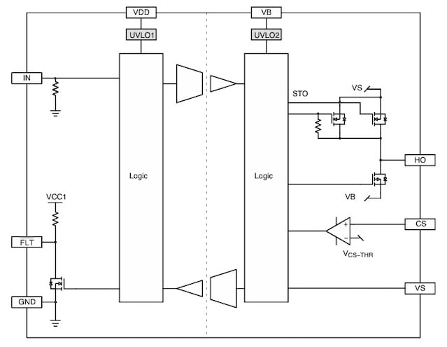
Figure 2. Simplified block diagram of the NCD57085 gate driver IC. Image used courtesy of onsemi
Overcurrent protection is handled through the current sense (CS) pin. A 22 mΩ/3 W shunt resistor (R14, SMD size 2512) is placed in the IGBT emitter path. When the voltage across the shunt exceeds the 250 mV internal threshold, the driver performs a soft turn-off to limit stress on the IGBT, and pulls the fault output low. The shunt resistor value can be selected based on the application’s maximum allowable load current. A 1% tolerance resistor in size 4527 or 2512 is recommended.
The module is well-suited for motor control, automotive power converters, UPS systems, industrial power supplies, HVAC drives, pumps, fans, and PTC heater circuits.
Schematic and Bill of Materials
Figure 3 shows the schematic for the Isolated Half-Bridge module.
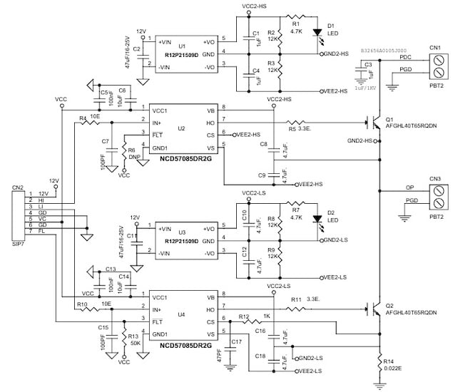
Figure 3. Schematic for the Isolated Half-Bridge with Current Sense.
The bill of materials is shown in Table 1.
Table 1. BOM for the Isolated Half-Bridge with Current Sense.
| REF | DESCRIPTION | QTY | MFG | SUPPLIER | PART NO. |
| CN1, CN3 | 2 PIN SCREW TERMINAL PITCH 7.62MM | 2 | Wurth | Digikey | 732-691254410002-ND |
| CN2 | 7 PIN MALE HEADER PITCH 2.54MM | 1 | Wurth | Digikey | 732-5320-ND |
| C1, C4, C10, C12 | 4.7uF/35V CERAMIC SMD SIZE 0805 | 4 | Yageo/Murata | Digikey | |
| C2, C11 | 47uF/16-25V CERAMIC SMD SIZE 1210 | 2 | Yageo/Murata | Digikey | |
| C3 | 1uF/1kV | 1 | Epcos | Digikey | 495-B32656A0105J000-ND |
| C5, C13 | 100nF/50V CERAMIC SMD SIZE 0805 | 2 | Yageo/Murata | Digikey | |
| C6, C14 | 10uF/25V CERAMIC SMD SIZE 0805 | 2 | Yageo/Murata | Digikey | |
| C7, C15 | 100pF/50V CERAMIC SMD SIZE 0805 | 2 | Yageo/Murata | Digikey | |
| C8, C9, C16, C18 | 4.7uF/35V CERAMIC SMD SIZE 1206 | 4 | Yageo/Murata | Digikey | |
| C17 | 47pF/50V CERAMIC SMD SIZE 0805 | 1 | Yageo/Murata | Digikey | |
| D1, D2 | LED RED SMD SIZE 0805 | 2 | Osram | Digikey | 475-1278-1-ND |
| Q1, Q2 | AFGHL40T65RQDN IGBT TO-247 | 2 | Onsemi | Digikey | 488-AFGHL40T65RQDN-ND |
| R1, R7 | 4.7K 5% SMD SIZE 0805 | 2 | Yageo/Murata | Digikey | |
| R2, R3, R8, R9 | 12K 5% SMD SIZE 0805 | 4 | Yageo/Murata | Digikey | |
| R4, R10 | 10E 5% SMD SIZE 0805 | 2 | Yageo/Murata | Digikey | |
| R5, R11 | 3.3E 5% SMD SIZE 1206 | 2 | Yageo/Murata | Digikey | |
| R6 | DNP | 1 | Digikey | ||
| R12 | 1K 5% SMD SIZE 0805 | 1 | Yageo/Murata | Digikey | |
| R13 | 49.9K 1% SMD SIZE 0805 | 1 | Yageo/Murata | Digikey | |
| R14 | 0.022E/3W 1% SMD SIZE 2512 | 1 | Vishay Dale | Digikey | WSR3R0220FEA-ND |
| U1, U3 | R12P21509D ISOLATED DC-DC | 2 | Recom Power | Digikey | 945-2800-ND |
| U2, U4 | NCD57085DR2G GATE DRIVER | 2 | onsemi | Digikey | 488-NCD57085DR2GCT-ND |
Connections
Figure 4 shows the connection diagram. Refer to the descriptions below for each connector.
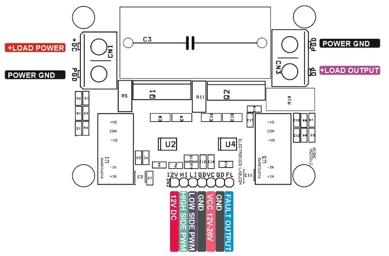
Figure 4. Connection diagram for the Isolated Half-Bridge module.
CN1 — DC Bus Input (2-pin screw terminal):
- Pin 1 = +Load Power (DC bus positive)
- Pin 2 = Power GND
CN2 — Control Header (7-pin, 2.54 mm pitch):
- Pin 1 = 12 V DC
- Pin 2 = High-Side PWM Input
- Pin 3 = Low-Side PWM Input
- Pin 4 = GND
- Pin 5 = VCC (12–20 V gate driver supply)
- Pin 6 = GND
- Pin 7 = Fault Output (active low, normally high)
CN3 — Load Output (2-pin screw terminal):
- Pin 1 = +Load Output
- Pin 2 = Power GND
D1, D2:
- D1 = Upper (high-side) DC-DC converter power LED
- D2 = Lower (low-side) DC-DC converter power LED
PCB Files
The PCB layout is shown in Figure 5. Gerber files for fabrication are available for download below. The PCB is 68.90 × 52.07 mm.
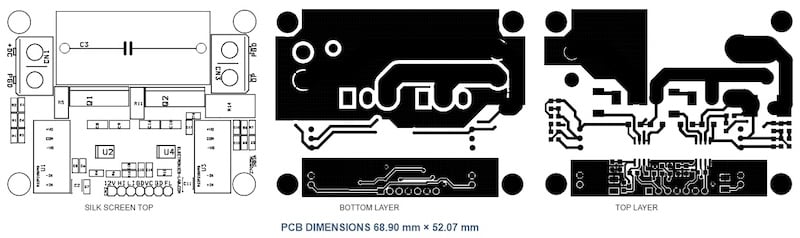
Figure 5. PCB layout: silk screen top, bottom layer, and top layer.
Isolated Half-Bridge Gerber Files
You can download the layout files for this project here:
Isolated Half-Bridge Gerber Files
Except where noted, all images used courtesy of Rajkumar Sharma