 Facebook
 Google
 GitHub
 Linkedin
Harnessing High-Frequency Sound: A New Ultrasonic Controller from Texas Instruments
You can do a lot with ultrasound, and whatever you’re doing will be easier with a highly integrated IC such as the PGA460-Q1.
You can do a lot with ultrasound, and whatever you’re doing will be easier with a highly integrated IC such as the PGA460-Q1, to be released in June.
The basic concept of ultrasound is simple: You generate sound waves at frequencies that humans can’t hear. The sound waves reflect off of something. You detect the reflections and interpret them according to the application.
As usual, though, there are various details that you have to contend with. And if you were to judge based on the length of the datasheet for the PGA460-Q1 (114 pages), you would probably conclude that these details are not exactly trivial.
As you can see in the application diagram, you don’t need many external components:

All images from Texas Instruments (PDF)
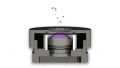
One thing you will undoubtedly need is an ultrasonic transducer. This is the device that first converts electrical signals into high-frequency sound waves, and then converts reflected sound waves back into electrical signals.
The PGA460-Q1 is flexible with regard to transducer selection, and it makes things quite convenient for the board designer: driving frequency, driving current limit, and filter coefficients are all adjustable. (Note: the datasheet says that the “device meets most transducer requirements by adjusting . . . ,” which implies that something is occurring automatically, but these adjustments are at least partially based on user-defined configuration data.)
The Driver
Another important component is the transformer that you might use as an interface between the PGA460-Q1’s driver pins and the transducer.

The transformer approach offers better distance performance because you can provide a higher voltage for the transducer, and I get the impression that this is generally the preferred configuration. However, in applications that don’t involve harsh environmental conditions, you have the option of using an “open-top” transducer. With an open-top, you are more likely to achieve adequate range without the extra drive voltage enabled by the transformer.
The non-transformer approach involves either a half-bridge or full-bridge drive circuit. Only the low-side drivers are included in the PGA460-Q1, so you need at least one external FET.

The Receiver
In the two previous diagrams, you can see the circuitry required to convert received ultrasound into usable digital signals. It’s not exactly extensive or complex. In fact, it appears to consist of . . . two capacitors (in addition to the transducer).
However, the capacitors are just the appeasement components that the IC designers leave out to ensure that we ordinary mortals don’t feel completely useless. It takes a lot more than two caps to process the reflected signals:

But we’re not done yet! Not even close. The above diagram covers only the analog and analog-to-digital portions of the signal chain. You also get a generous dose of integrated DSP.

The bottom line here is that the PGA460-Q1 uses a combination of digital and analog signal processing to facilitate object detection based on the reflected ultrasound. The result of all this is digital data that is available to the system controller through a serial communication interface.
Applications
So what exactly can you do with the PGA460-Q1? It’s intended primarily for automotive applications—parking-assistance systems, collision warnings, door sensors. The part is AEC-Q100 qualified, which means that it is compliant with the reliability standards published by the Automotive Electronics Council.
However, many applications could benefit from the ultrasonic functionality that becomes quite convenient when you have an advanced chip such as this one. Two interesting possibilities are obstacle detection for robots and landing-assistance systems for drones. I don’t know much about drones, but I’m guessing that high-precision distance-to-the-ground measurements could make the landing process more . . . predictable (but maybe less exciting).
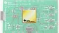
Yes, There’s an Eval Board
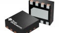
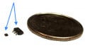
In a downright arresting rupture with recent trends, the PGA460-Q1 does not come in a grain-of-sand-scale package with microscopic “lands” that are almost impossible to solder by hand. It’s a TSSOP, and furthermore, the number of pins (sixteen) is entirely reasonable.
Nevertheless, you might still prefer to get started with an evaluation module. (If you do design your own board, remember to take a good look at the recommended layout.)

The list of registers is quite long and, in the early stages of the design process, you’ll probably be glad that you have a fully functional board and an accompanying GUI.
The PGA460-Q1 will be available in June. Are you aware of comparable ultrasound control/processing ICs? Do you have any recommendations for ultrasonic detection systems? Feel free to share your thoughts in the comments.
Related Content


Very interesting. What is the range of frequencies possible?
I’m only interested in producing an adjustable output. Where can I find a schematic for this if possible?