 Facebook
 Google
 GitHub
 Linkedin
How the Boost PFC Converter Circuit Improves Power Quality
A boost power factor correction (PFC) converter can significantly improve both the power factor and the harmonic distortion.
Linear power supplies, even ones with passive filtering have low power factor and high harmonic currents. Learn about the boost power factor correction (PFC) converter, a circuit that can improve the power quality of power supplies.
Related Information
- Calculating Power Factor
- Practical Power Factor Correction
- Power Factor, THD, and Why Linear Power Supplies Fail to Meet Power Standards
All electronic devices require power supplies to convert the AC voltage from the grid to DC voltage for electronics. Linear power supplies, even ones with passive filtering, have a low power factor and introduce harmonic currents into the system.
The overall effect of a single power supply is not large, but when you consider the millions of such supplies in use, the combined effect on power quality of these power supplies can be substantial. We can improve this situation by using power supplies that incorporate power factor correction circuitry, which increases the power factor and reduces harmonic currents. The boost power factor correction converter is one circuit that can be added to power supplies to significantly improve their power quality.
Power Factor and Power Factor Correction
One type of power factor correction (PFC) involves passive correction, where the reactive power of a system is compensated by adding a component that will use an equal but opposite amount of reactive power. For example, if a load is inductive with a reactive power of 1.754 kVAR, then the system would require a capacitive load with a reactive power of 1.754 kVAR to oppose the inductance.
One way to implement this kind of power factor correction is to have a large bank of capacitors that can be switched into the circuit when needed. This type of power factor correction works well for linear loads on large scales where the cost of the power factor correction system can be absorbed by the size and cost of the overall system.
On much smaller scales—for example, individual power supplies—power factor is also important. It's important not because any individual power supply has a large effect on the system, but because there are so many power supplies. Even more challenging is the fact that these power supplies are non-linear loads, so the power factor cannot be corrected by simply adding reactive components (i.e., capacitors or inductors).
To ensure that electronic devices do not have a significant cumulative effect on the power factor of the grid, international standards such as EN61000-3-2 and Energy Star 80 Plus set limits on the power-factor degradation and harmonic distortion introduced by power supplies.
A previous article showed that simple passive filters are not enough to adequately improve the power factor or harmonic distortion. Instead, we must use an active power factor circuit that forces the AC current to track the AC voltage.
The Boost Power Factor Correction Converter
One of the most common active PFC circuits is called the boost PFC converter, which is a relatively simple and low-cost circuit. The only extra components that are required beyond the ones used in a linear AC-DC converter are a switch (usually a FET), a diode, and an inductor.
Figure 1 below shows a boost PFC converter. You can see that it is essentially a linear power supply with a boost converter inserted between the rectifier and the filter capacitor.
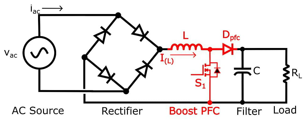
Figure 1. Boost PFC converter circuit
The general goal of the boost PFC converter is to turn the switch (S1) off and on rapidly and with a varying duty cycle in order to make the input current (iac) sinusoidal and in phase with the input voltage (vac).
Boost PFC Converter Operation
The boost PFC circuit cycles rapidly between two states. The first state occurs when S1 is closed, as shown in Figure 2. When in this state, the inductor is being energized by the AC side of the circuit via the rectifier, and thus the inductor current will be increasing. At the same time, diode Dpfc becomes reverse biased (because its anode is connected to ground through S1), and energy is provided to the load by the capacitor.

Figure 2. Boost PFC converter with the switch (S1) closed
Figure 3 shows the second state, which occurs when S1 is open. In this state, the inductor de-energizes (the current decreases) as it supplies energy to the load and for recharging the capacitor.
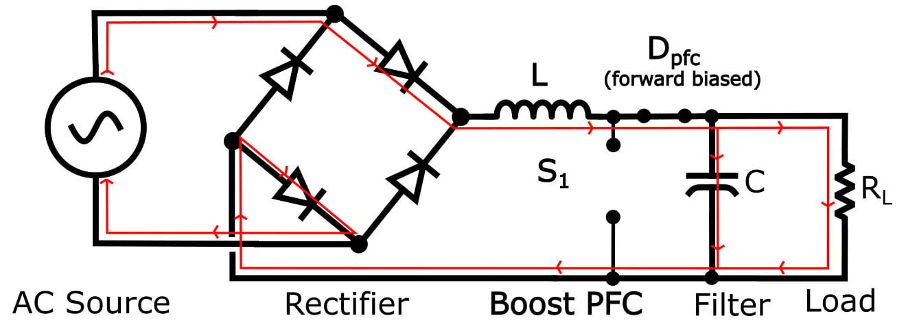
Figure 3. Boost PFC converter with the switch (S1) open
(Note that both Figure 2 and Figure 3 show only the positive half of the input voltage cycle. The negative half would be identical except that current would be flowing through the other two diodes of the rectifier.)
The cycling between the two states is done at a high frequency that is at least in the tens of kHz, but is often an order of magnitude (or even more) higher than that. The cycling back and forth between states is done rapidly and in a manner that both maintains a constant output voltage and controls the average inductor current (and subsequently the average AC current).
Since the inductor current is increasing in state 1 and decreasing in state 2, the duty cycle determines the amount of time the inductor current increases versus the amount of time the inductor current decreases. Thus, by varying the duty cycle, the average inductor current can be adjusted. By making this average current track the expected current, you can get a significant improvement in power factor and total harmonic distortion (THD).
For an ideal system, the expected inductor current would be a rectified sine wave and the expected AC input current would be a sine wave. Because of the switching nature of the system and the difficulty in obtaining perfect tracking of the expected current, the AC input current (Iac) will not be an ideal sine wave and the inductor current (I(L)) will not be an ideal rectified sine wave, but will instead look something like this:
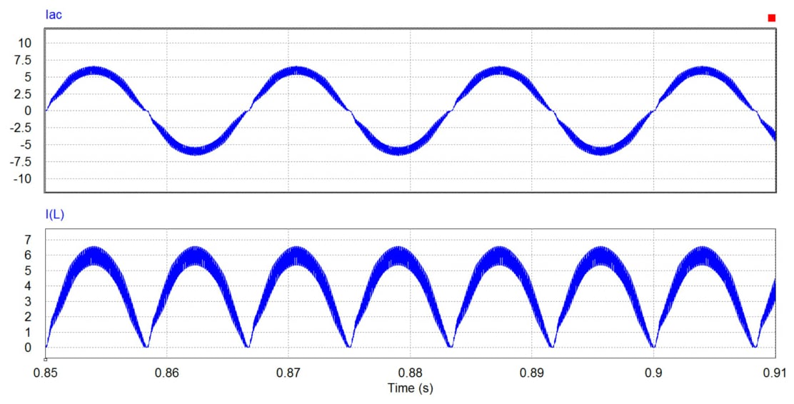
Figure 4. AC current and inductor current of a boost PFC converter
These currents are the general shape that they should be (sinusoid/rectified sinusoid), but one thing that stands out is that the lines of the signals look thick. This thickness occurs because during one cycle the current ramps up and then ramps down as the average current is controlled to track the reference sinusoidal voltage.
Zooming in on the inductor current reveals the repeatedly increasing and decreasing currents of the inductor as the system switches between the two states.
.jpg)
Figure 5. Zoomed-in view of the inductor current in a boost PFC converter
Boost PFC Control System
Closed-loop control is needed to ensure that the output voltage is maintained and the AC current is sinusoidal and in phase with the AC voltage. It is beyond the scope of this article to describe how the control system is designed, but Figure 6 gives you a general idea of the overall system; it shows a boost PFC circuit with a controller block that accepts four inputs and generates a pulse-width-modulated (PWM) output applied to the gate of S1.

Figure 6. Boost PFC converter circuit with control system
The control system shown in Figure 6 requires three things:
- measurement of the output voltage (Vdc) to ensure that it is maintained at the reference level (Vref)
- measurement of the AC voltage to provide a reference for the inductor current
- measurement of the average inductor current to ensure that it tracks the rectified AC voltage
The control system would typically be a PI or PID control system that ensures that the difference between the reference signals and the required signals is as small as possible.
The results of a successful design are improved power factor and THD, as well as a regulated output voltage. The AC voltage and current for a boost PFC converter are shown in Figure 7.
.jpg)
Figure 7. AC voltage and current
You can see that the current and voltage are close to being in phase and that the current has a general sinusoidal shape with minimal distortion.
Analysis of this system indicates that the power factor is just under 0.99 and the THD is about 10%. These numbers indicate that the power quality is quite good, and they would be sufficient for meeting the harmonic current requirements of IEC 61000-3-2 as well as the power factor requirements of Energy Star 80 Plus.
Conclusion
Linear power supplies have a negative effect on the power quality of an electrical system. Adding passive filters to the power supply can improve the power quality but not enough to meet power quality specifications such as those of IEC 61000-3-2 and Energy Star 80 Plus. Active power factor correction is necessary in order to meet those specifications, and one of the cheapest and most common ways to implement active power factor correction is by using a boost PFC converter.
The boost PFC converter uses a switching element to force the input AC current to be sinusoidal and in phase with the input voltage. The example used in this article showed that significant improvement to the power quality of a power supply can be obtained by using a boost PFC converter.


Thank you for your competent treatment of this (largely) underappreciated topic! 😊
Sincerely
HP