 Facebook
 Google
 GitHub
 Linkedin
Introduction to Battery Management Systems
Learn the high-level basics of what role battery management systems (BMSs) play in power design and what components are necessary for their basic functions.
Nowadays, Li-ion batteries reign supreme, with energy densities up to 265 Wh/kg. They do, however, have a reputation of occasionally bursting and burning all that energy should they experience excessive stress. This is why they often require battery management systems (BMSs) to keep them under control.
In this article, we'll discuss the basics of the BMS concept and go over a few foundational parts that make up the typical BMS.
Basic BMS Configurations
In Figure 1, we see the basic blocks of how a BMS can look while serving the function of preventing major battery malfunctions.
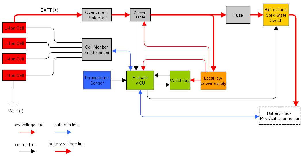
Figure 1. A typical BMS block diagram
This example BMS can handle four Li-ion cells in series. A cell monitor reads all the cell voltages and evens out the voltage among them: this function is called balancing (more on that later). This is controlled by an MCU that handles telemetry data, as well as switch manipulation and balancing strategy.
In practice, the market offers different solutions for simpler designs, including for single cells with no balancing or MCUs, as shown in Figure 2.
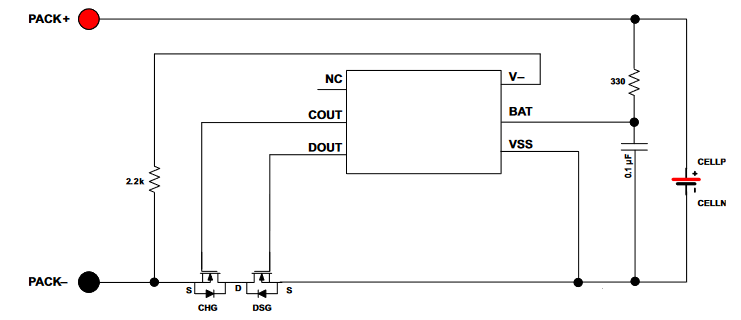
Figure 2. A simple battery manager. Image used courtesy of Texas Instruments
The downside of these simpler systems is that a designer is bound to what the given part offers (e.g., a high or low side switch) without customization.
When using more cells, a balancing system is needed. Simple schemes that still function without an MCU exists, as shown in Figure 3.
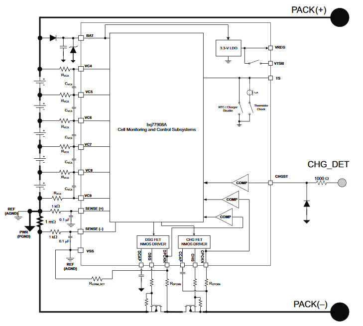
Figure 3. An MCU-independent cell balancer. Image used courtesy of Texas Instruments
When using bigger battery packs or anything which requires cells in series or a fuel gauge calculation, an MCU is needed. The most integrated (and therefore low cost) solution is the one in Figure 4.
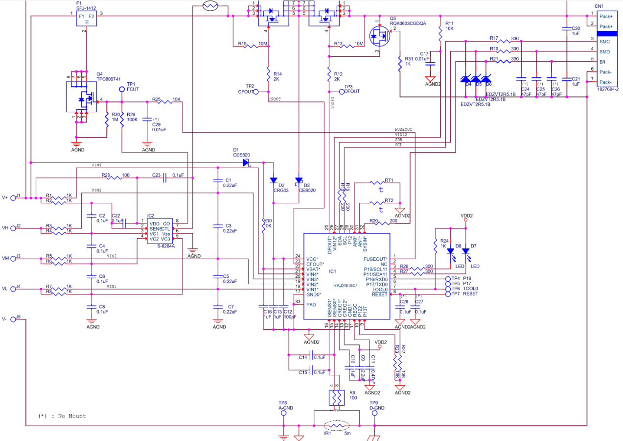
Figure 4. A commercial BMS. Image used courtesy of Renesas
This is a BMS that uses an MCU with proprietary firmware running all of the associated battery-related functions.
The Building Blocks: Battery Management System Components
Look back at Figure 1 to get an overview of the fundamental parts crucial to a BMS. Now, let's go through the main parts of Figure 4 in a bit more detail to understand the various elements involved in a BMS block diagram.
Fuse
When a violent short circuit occurs, the battery cells need to be protected fast. In Figure 5, you can see what's known as a self control protector (SCP) fuse, which is mean to be blown by the overvoltage control IC in case of overvoltages, driving pin 2 to ground.
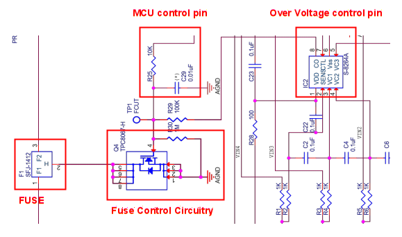
Figure 5. SCP fuse and control of a commercial BMS
The MCU can communicate the blown fuse's condition, which is why the MCU power supply has to be before the fuse.
Current Sensing/Coulomb Counting
Here is implemented a low side current measurement, allowing direct connection to the MCU.
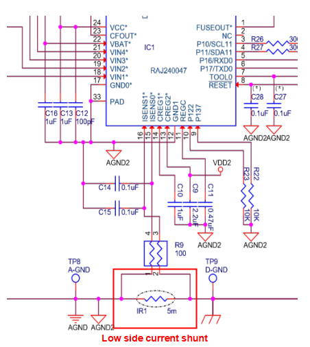
Figure 6. Typical low current sense of a commercial BMS
Keeping a time reference and integrating the current over time, we obtain the total energy entered or exited the battery, implementing a Coulomb counter. In other words, we can estimate the state of charge (SOC, not to be confused with a system-on-chip) by using the following formula:
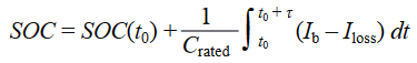
where
- $$SOC(t_0)$$ is the initial SOC (in Ah)
- $$C_{rated}$$ is the rated capacity (in Ah)
- $$I_b$$ is the battery current
- $$I_{loss}$$ takes into account the cell reaction losses
- τ is the averaging period of the electric current samples
Thermistors
Temperature sensors, usually thermistors, are used both for temperature monitor and for safety intervention.
In Figure 7, you can see a thermistor that controls an input of the overvoltage control IC. This artificially blows the SCP (the fuse shown in Figure 5) without MCU intervention.
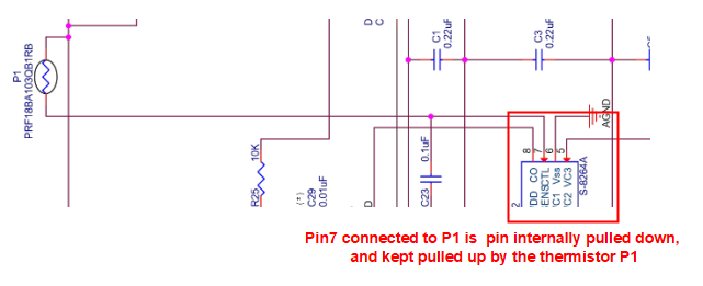
Figure 7. A thermistor can control the SCP, in case of severe thermal problems
Figure 8 shows two additional thermistors for telemetry.
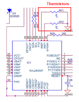
Figure 8. Thermistors used by the firmware
Main Switch
To act as switches, MOSFETs need their drain-source voltage to be $$V_{ds} \leq V_{gs} - V_{th}$$. The electric current in the linear region is $$I_d = k \cdot (V_{gs} - V_{th}) \cdot V_{ds}$$, making the resistance of the switch $$R_{MOS} = 1 / [k \cdot (V_{gs} - V_{th})]$$.
It's important to drive the $$V_{gs}$$ accordingly to ensure low resistance and hence low losses.
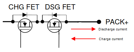
Figure 9. Battery pack main switch (NMOS, high-side)
NMOS types are used also on high side switches through a charge pump, since normally they have lower $$R_{MOS}$$.
Balancer
Battery cells have given tolerances in their capacity and impedance. So, over cycles, a charge difference can accumulate among cells in series.
If a weaker set of cells has less capacity, it will charge faster compared to others in series. The BMS has to therefore stop other cells from charging, or else the weaker cells will get overcharged, as seen in Figure 10.
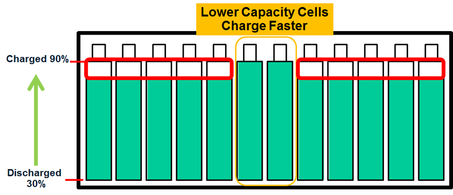
Figure 10. Lower capacity cells impeding pack full charging. Image used courtesy of Analog Devices
Conversely, a cell can get discharged faster, risking that cells going under its minimum voltage. In this instance, a BMS without a balancer has to stop the power delivery earlier, as seen in Figure 11.
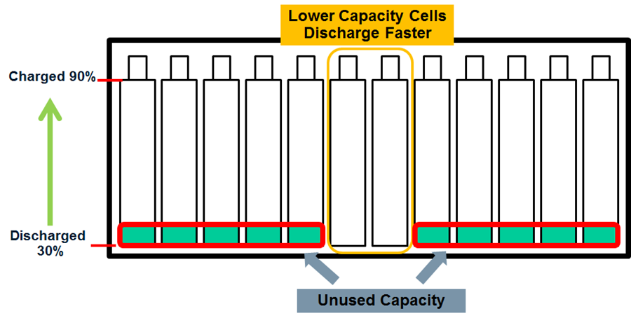
Figure 11. Lower capacity cells impeding usage of full pack energy. Image used courtesy of Analog Devices
A circuit like the one in Figure 12 will discharge the cell with higher SOC (state of charge) as shown in Figure 10 at the level of the other cells in series. This is accomplished by using a passive method of balancing called charge shunting.
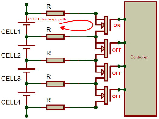
Figure 12. Example of passive balancing strategy
Because current flows through the transistor in the ON state and dissipates through R, and because the voltage reference is CELL1 (a negative pole), only such a cell will discharge its energy excess.
This article has aimed to introduce the basic concept of a battery management system and introduce the basic components used in their design. Hopefully, you now have a better understanding of what a battery management system is meant to accomplish and how it can be used in a power design.
If you have additional concepts you'd like to learn more about regarding BMS design, please leave a comment below.
Related Content


Good read. I had remind myself of a MOSFET’s ON condition too. Many articles I’ve seen show batteries in series. How do you manage many single cells in parallel? Would they all need their individial manager?
What about a hybrid fuel cell energy management !