 Facebook
 Google
 GitHub
 Linkedin
Guide to USB-C Pinout and Features
This introductory article will look at some of the most important features of the USB-C standard.
Do you know your way around a USB Type-C connector? This article lays out the anatomy of the USB Type-C pinout and briefly touches on its various modes.
USB Type-C is a specification for a USB connector system that is gaining popularity across smartphones and mobile devices and is capable of both power delivery and data transmission.
Unlike its USB predecessors, it's also flippable—so you don't need to try three times to plug it in.
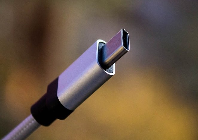
A USB Type-C port. Image used courtesy of Denys Vitali
This introductory article will look at some of the most important features of the USB-C standard. Before diving into the pinout and explaining what each is capable of, we'll quickly take a high-level view of what USB-C is and what it's best at.
What Is USB-C?
The USB-C is a relatively new standard which aims to provide high-speed data transfer up to 10Gb/s along with power flow capability of up to 100W. These features can make the USB-C a truly universal connectivity standard for the modern devices.
USB-C or USB Type-C?
These two terms are generally interchangeable (we'll use both throughout this article). Though USB-C is more commonly used, USB Type-C is the official name of the standard as listed on USB.org.
USB-C Features
The USB-C interface has three main features:
- It has a flippable connector. The interface is designed in a way that the plug can be flipped relative to the receptacle.
- It supports USB 2.0, USB 3.0 and USB 3.1 Gen 2 standards. Moreover, it can support third-party protocols such as DisplayPort and HDMI in a mode of operation called Alternate Mode.
- It allows the devices to negotiate and choose an appropriate level of power flow through the interface.
In the following sections, we’ll see how these features are provided by the USB Type-C standard.
The USB Type-C Receptacle/Plug Pins
The USB Type-C connector has 24 pins. Figures 1 and 2, respectively, show the pins for the USB Type-C receptacle and plug.
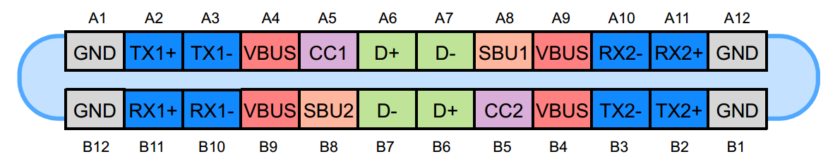
Figure 1. The USB Type-C receptacle. Image used courtesy of Microchip
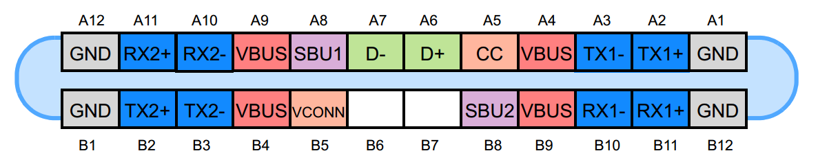
Figure 2. The USB Type-C plug. Image used courtesy of Microchip
USB 2.0 Differential Pairs
The D+ and D- pins are the differential pairs used for the USB 2.0 connectivity. There are two D+ pins and two D- pins in the receptacle.
However, the pins are connected to each other and there’s actually only one USB 2.0 data differential pair available for use. The redundancy is included only to provide a flippable connector.
Power and Ground Pins
The VBUS and GND pins are power and the return paths for the signals. The default VBUS voltage is 5 V but the standard allows the devices to negotiate and choose a VBUS voltage other than the default value. The Power Delivery allows VBUS to have a voltage up to 20 V. The maximum current could be also raised up to 5 A. Hence, the USB Type-C could deliver a maximum power of 100 W.
The high power flow could be useful when charging a large device such as a notebook computer. Figure 3 shows an example from RICHTEK where a buck-boost converter is used to generate the appropriate voltage requested by the notebook computer.
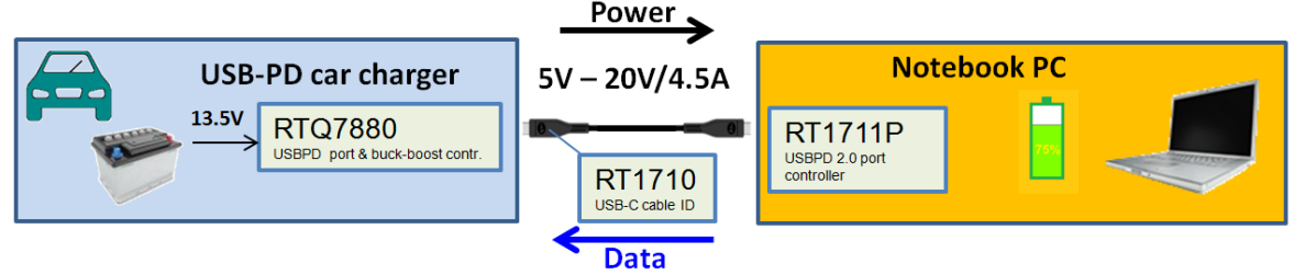
Figure 3. Charging a notebook PC using a car charger and a USB-C cable. Image used courtesy of Richtek
Note that the power delivery technology makes USB Type-C more versatile than the older standards because it makes the power level adaptable with the needs of the load. You can charge both of your smartphone and notebook using the same cable.
The RX and TX Pins
There are two sets of RX differential pairs and two sets of TX differential pairs.
One of these two RX pairs along with a TX pair could be used for the USB 3.0/USB 3.1 protocol. Since the connector is flippable, a multiplexer is required to correctly re-route the data on the employed differential pairs through the cable.
Note that a USB Type-C port could support USB 3.0/3.1 standards but the minimum feature set of USB Type-C doesn’t include USB 3.0/3.1. In such cases, the RX/TX pairs are not used by the USB 3.0/3.1 connectivity and could be used by other USB Type-C functionalities such as the Alternate Mode and the USB Power Delivery protocol. These functionalities may utilize even all of the available RX/TX differential pairs.
The CC1 and CC2 Pins
These pins are the Channel Configuration pins. They perform a number of functions such as cable attachment and removal detection, receptacle/plug orientation detection, and current advertisement. These pins could be also used for the communications required by the Power Delivery and Alternate Mode.
Figure 4 below shows how the CC1 and CC2 pins reveal the receptacle/plug orientation. In this figure, DFP stands for Downstream Facing Port. This is the port acting as either the host in data transmission or the source for power. UFP denotes Upstream Facing Port, which is the device connected to the host or the power consumer.
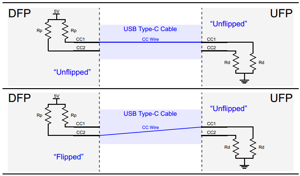
Figure 4. Upstream and downstream facing ports. Image used courtesy of Microchip
The DFP pulls up the CC1 and CC2 pins through the Rp resistors but the UFP pulls them down through Rd. If no cable is attached, the source sees a logic high at CC1 and CC2 pins. Connecting the USB Type-C cable creates a current path from 5-V supply to ground. Since there’s only one CC wire inside the USB Type-C cable, only one current path is formed. For example, in the upper graphic of Figure 4, the CC1 pin of the DFP is connected to the CC1 pin of the UFP. Hence, the DFP CC1 pin will have a voltage lower than 5 V but the DFP CC2 pin will be still at the logic high. Therefore, monitoring the voltage on the DFP CC1 and CC2 pins, we can determine cable attachment and its orientation.
In addition to the cable orientation, the Rp-Rd path is used as a way of communicating information about the source current capabilities. To this end, the power consumer (UFP) monitors the voltage on the CC line. When the voltage on the CC line has its lowest value (about 0.41 V), the source can provide the default USB power which is 500 mA and 900 mA for the USB 2.0 and USB 3.0 respectively. When the CC line voltage is about 0.92 V, the source can provide a current of 1.5 A. The highest CC line voltage which is about 1.68 V corresponds to the source current capability of 3 A.
The VCONN Pin
As mentioned above, the USB Type-C aims to provide blazing fast data transfer speeds along with high levels of power flow. These features may require the use of special cables that are electronically marked by employing a chip inside. Besides, some active cables utilize a re-driver chip to strengthen the signal and compensate for the losses incurred by the cable, etc. In these cases, we can power the circuitry inside the cable by applying a 5-V, 1-W power supply to the VCONN pin. This is shown in Figure 5.
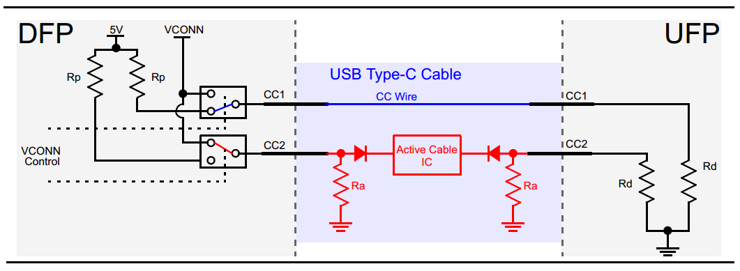
Figure 5. The circuitry inside the cable is powered by applying a 5-V, 1-W power supply to the VCONN pin. Image used courtesy of Microchip
As you can see, the active cable uses the Ra resistors to pull down the CC2 pins. The value of Ra is different from Rd so the DFP is still able to determine the cable orientation by examining the voltage on the DFP CC1 and CC2 pins. After determining the cable orientation, the channel configuration pin corresponding to the “Active Cable IC” will be connected to a 5-V, 1-W supply to power the circuitry inside the cable. For example, in Figure 5, the valid Rp-Rd path corresponds to the CC1 pin. Hence, the CC2 pin is connected to the supply denoted by VCONN.
The SBU1 and SBU2 Pins
These two pins correspond to low-speed signal paths that are used only in the Alternate Mode.
The USB Power Delivery
Now that we are familiar with the pinning of the USB-C standard, let’s have a brief look at the USB Power Delivery.
As mentioned above, the devices using the USB Type-C standard can negotiate and choose an appropriate level of power flow through the interface. These power negotiations are achieved through a protocol called USB Power Delivery which is a single wire communication over the CC line discussed above. Figure 6 below shows an example USB Power Delivery where the sink sends requests to the source and adjusts the VBUS voltage as needed. At first, a 9-V bus is requested. After the source stabilizes the bus voltage at 9 V, it sends a “power-supply-ready” message to the sink. Then, the sink requests a 5-V bus and the source provides it and sends a “power-supply-ready” message again.

Figure 6. Example of USB power delivery where the sink sends requests to the source and adjust VBUS as needed. Image courtesy of Richtek
It’s important to note that the “USB Power Delivery” is not just about the power delivery related negotiations, other negotiations, such as those related to the Alternate Mode, are done using the Power Delivery protocol on the CC line of the standard.
Alternate Modes
This mode of operation allows us to implement third-party protocols, such as DisplayPort and HDMI, using the USB Type-C standard. All Alternate Modes must at least support a USB 2.0 and USB Power Delivery connection. For more information, please refer to this TI document.
Conclusion
The USB Type-C has interesting features. It supports a blazing fast data transfer speed of up to 10 Gb/s and high power flow of up to 100 W. These along with a flippable connector can make the USB Type-C a truly universal standard for the modern devices.
To see a complete list of my articles, please visit this page.
Related Content


If the Rx and Tx pins were designed with full reversible redundancies, could the data transfer speeds be much faster?