Facebook
 Google
 GitHub
 Linkedin
Junction-to-Case Thermal Resistance in Thermal Design
Learn about an important thermal metric for designing the interface between an IC package and a heat sink.
The lifetime of a semiconductor device can reduce significantly when it is operated at temperatures above the rated values. Hence, the thermal performance should be carefully evaluated both at the device and system levels.
In a previous article, we examined the junction-to-ambient thermal resistance, θJA. We saw that θJA can be used for comparing packages from different vendors as well as achieving a first-order approximation of the thermal performance of an application-specific design.
In this article, we’ll take a look at the junction-to-case thermal resistance θJC and how this data can be used to evaluate the thermal performance of a design that attaches the package to a heatsink.
Junction-to-Case Thermal Resistance: θJC
θJC specifies the thermal resistance from junction to the case surface. To avoid confusion, manufacturers may specify the surface in consideration by giving this thermal data as θJC(Top) and θJC(Bot). These two are the thermal resistances from the junction to the case top and bottom surfaces, respectively.
The setup for measuring θJC is shown below.
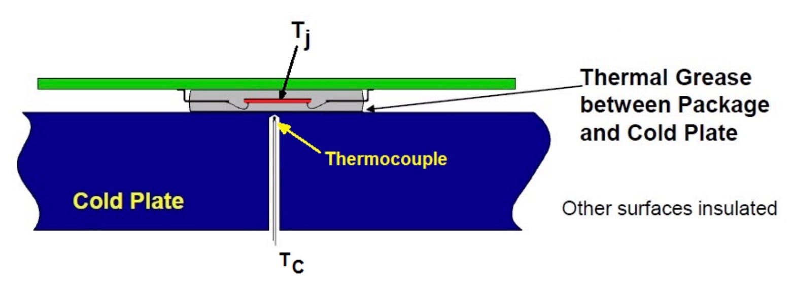
The measurement of RθJC (TI's representation of θJC). Image courtesy of Texas Instruments.
The reference point for measuring the case temperature, TC, is the hottest point on the package which is usually the center of the package surface or the lid of the device.
A heatsink is mounted on the package surface where TC is to be measured and other surfaces of the test coupon are insulated to minimize uncontrolled heat loss from these surfaces. The heatsink is a copper cold plate with circulating constant temperature fluid and can absorb heat easily. There is a layer of thermal grease between the package and the heatsink to couple the two thermally.
Calculating Junction Temperature from TC and θJC
The key point is that the above measurement process ensures that almost all of the heat generated by the device flows from the junction to the case surface of interest (the top surface for θJC(Top) and the bottom surface for the θJC(Bot) measurement).
Having TC and θJC, we can calculate the junction temperature as:
$$T_J = T_C + P_T \times θ_{JC}$$
Equation 1
where PT denotes the chip total power.
It is worthwhile to mention that the θJC(Bot) parameter is usually given for devices with an exposed thermal pad and specifies the heat transfer that takes place through this thermal pad.
Application of θJC
The main application of θJC is estimating the thermal performance of a given package when a heatsink is attached to it. Applications that employ an efficient heatsink resemble the above measurement setup and hence, Equation 1 can be used.
Exposed-pad plastic packages mounted on a thermally enhanced PCB is another example application where the above equation can be applied. However, without an efficient heatsink incorporated, only a portion of the heat generated in the chip will flow out of the package surface.
The rest of the heat, between 60-95%, can be convected and radiated off the PCB on which the device is mounted (as depicted below).
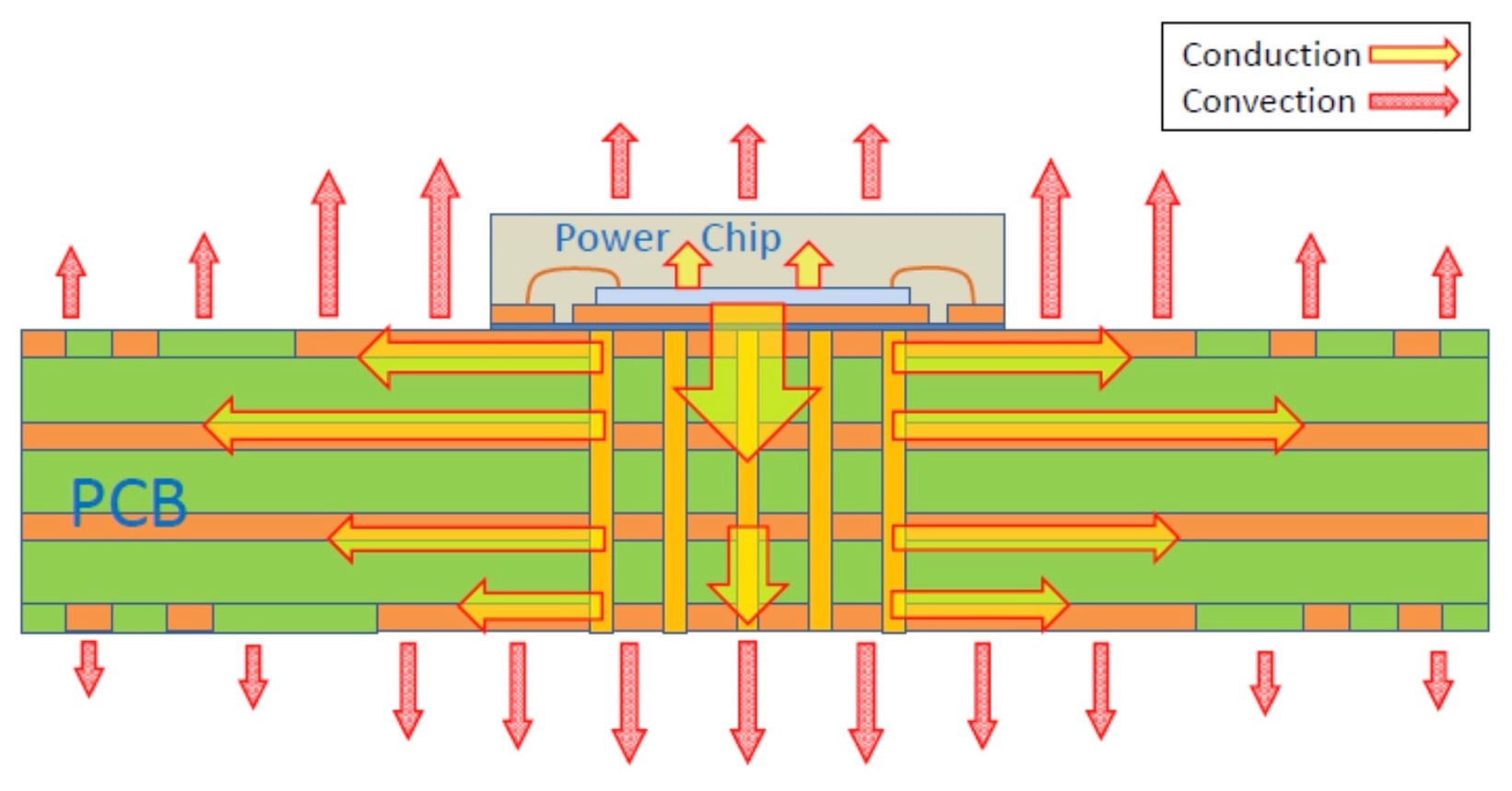
Image courtesy of ON Semiconductor.
In these cases, we should substitute PT in Equation 1 with the power that flows out of the package surface PS which is unknown to us. If we use the chip total power instead of PS, the equation will give a remarkably overestimated junction temperature.
Next: Designing with a Heat Sink
In the next article, we'll put this information into practice and discuss how to consider θJC when designing with or without a heat sink.
Related Content