Facebook
 Google
 GitHub
 Linkedin
Less EMI, More Available Board Space: A New Passive Filter from TDK
Why install three components when you could use one instead? You can simplify your layout with single-component passive filters, such as the MEM1005PP251T from TDK.
Why install three components when you could use one instead? You can simplify your layout with single-component passive filters, such as the MEM1005PP251T from TDK.
EMI (electromagnetic interference) is a serious concern these days. Wireless communication is increasingly pervasive, devices are smaller, clock speeds are higher, voltages are lower—all this places significant pressure on board designers. Products 1) must function reliably in whatever types of EMI environments they will be exposed to and 2) must not generate excessive levels of electromagnetic noise.
An interesting and somewhat sophisticated way of generating less EMI involves spreading the spectrum of digital signals. In this article, we’re going to discuss something more straightforward: the good-old-fashioned passive filter. More specifically, a Pi filter:

Diagram taken from this supplementary information sheet.
As you can see, the typical schematic depiction resembles the Greek letter π. Let’s take an intuitive look at this filter topology.
Pondering the Pi
If you ignore the first capacitor, we have a typical low-pass filter, but with an inductor instead of a resistor. The inductor gives us a two-pole response instead of the RC filter’s single-pole response. It also introduces peaking, which can be controlled by adding series resistance; the peaking results from resonance, i.e., cyclical movement of stored energy between the capacitor and inductor.
So at this point we have a low-pass filter with an input capacitor. The extra capacitor provides a low-impedance path to ground for high-frequency components in the input signal; it doesn’t, however, fundamentally change the filter’s frequency response. The Pi is still a low-pass filter.
An Alternative
The following plot shows you the frequency response for the MEM1005PP251T (let’s call it the MEM100) single-component Pi filter.

Plot taken from the MEM1005PP251T datasheet.
You may be wondering why I just declared the Pi topology to be a low-pass filter, considering that the plot indicates a band-stop (or “notch”) response. Well, notice that the upward slope begins at about 1.6 GHz; it’s actually caused by nonideal characteristics that become significant only at very high frequencies. If we were dealing with ideal capacitors and inductors and PCB traces, we’d have a standard low-pass response.
The fundamental problem here is that high frequencies have a coupling path from input to output—i.e., they are not attenuated as they should be. This app note from Texas Instruments indicates that the Pi filter’s notch response is due primarily to parasitic PCB capacitance.
In some applications, you really need that high-frequency attenuation. One example is RF circuits in which harmonic frequency components need to be suppressed. If you’re not satisfied with the performance of the Pi, you can try a T-type filter instead.

The T-type filter . . . it looks like the letter T.
This topology is discussed in the same TI app note; on page 5 you can see the improved frequency response provided by the T-type.
There’s also another topology called the Nje-type filter, because the circuit looks like the Cyrillic letter Њ . . . just kidding.
Not New, but Smaller
Pi filters are not exactly the most sophisticated of components, and as you can see from the circuit diagram above, they haven’t changed much in terms of the basic components—two caps, one inductor.
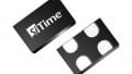
So why are we talking about the MEM100? Well, first, it’s convenient in terms of form factor—you’re getting a three-component circuit in one physical package. Furthermore, the MEM100 is tiny—it’s an 0402 device, with an extra terminal for the Pi filter’s ground connection:

Photo taken from the MEM1005PP251T datasheet.
This feature may not be intellectually thrilling, but size reduction is serious business these days. Also, the DC resistance is only 0.8 Ω; according to TDK, this represents a 69% reduction in DCR compared to “previous products.” The lower DCR allows for higher current through the device; with lower DCR, the same amount of current translates to lower power dissipation.
Applications
Pi filters are often used for suppressing unwanted frequency components in RF signals. The unwanted spectral content could be harmonics, as mentioned above, or it could be interference from other RF signals.
The MEM100 is specifically intended for EMI suppression in wireless devices such as smartphones and tablets. The frequency response offers significant attenuation from 700 MHz up into the gigahertz range, which means that it covers frequencies used by common wireless-communication standards.
Do you have any thoughts on the question of Pi filters vs. T-type filters? Leave us a comment and let us know.