Facebook
 Google
 GitHub
 Linkedin
Three Ways to Accelerate Cell Layout in DTCO
The device technology co-optimization (DTCO) methodology requires generating large numbers of layouts. This article introduces a few ways of speeding up this time-consuming process using automation.
Due to the increased scale of technology nodes, simple ring oscillator simulations no longer provide sufficient guidance for device, standard-cell, and BEOL architecture decisions. Foundries are therefore investing heavily in new ways of developing their process nodes and PDKs. One result of this has been the rise of device technology co-optimization (DTCO).
DTCO is a multi-stage methodology that spans from process assumptions through device architecture and BEOL definition. It also helps define design rules for lithographic and process limitations and validates them at the block-level RTL stage. Incorporating DTCO early in the technology definition ensures that architectural decisions help meet block-level Power-Performance-Area (PPA) targets.
Layout Creation: A Major Challenge in DTCO
DTCO begins by defining process assumptions, device architecture, and interconnect rules—including materials and geometries. The device is simulated, and BSIM-CMG compact models are then extracted from the device current and capacitance characteristics. Finally, a standard-cell library is created based on the constraints.
Cell layout considerations include placing and routing transistors, routing power-ground connections, and locating signal input and output pins. The logical correctness of the layouts is verified by comparing each layout to its schematic using Layout-Versus-Schematic (LVS) tools, while compliance with all design rules is confirmed through a Design-Rule-Check (DRC) stage.
Once the LVS and DRC-clean layouts are ready, the cell interconnect resistance-capacitance (RC) is extracted. It is modeled from material and geometric assumptions. The resulting RC netlist, along with the device models, is used to characterize the cells to generate liberty files with timing power models for block Place and Route simulations.
Since a cell library contains hundreds of standard cells, completing the layout manually for each architecture quickly becomes a huge time sink and makes a realistic DTCO turnaround impossible. To speed up evaluation, we need automated solutions for layout generation. In this article, we'll go over three ways of accelerating the layout phase:
- Hierarchical layout design. This lets engineers reuse block primitives so a few edits automatically propagate to all cells, dramatically reducing effort.
- Text-based GDS (GDT). This provides a human-readable format that enables easier parsing, editing, and text-diff comparison of layouts.
- Python gdspy. This offers a scriptable solution for bulk layout manipulation, which is especially useful for flat, non-hierarchical libraries.
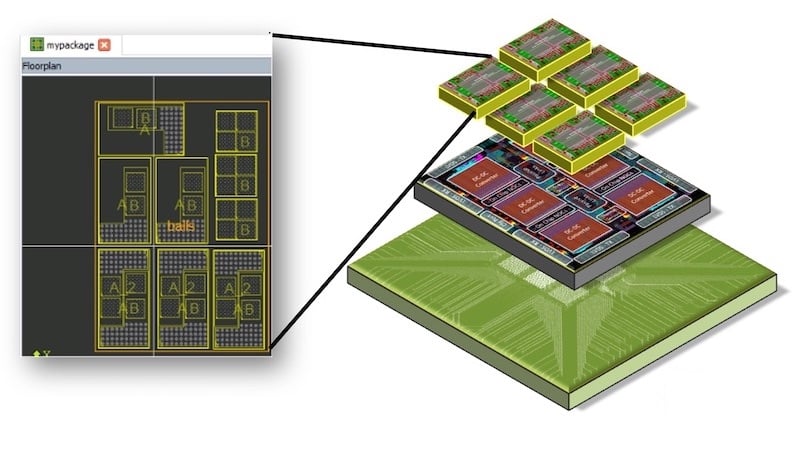
Hierarchical Design for Layout Creation
Instead of drawing each transistor and interconnect from scratch for every cell-architecture option, layout engineers can create a hierarchy of reusable blocks that are instantiated in standard cells. Since any change in the hierarchical block shows up in all the standard cells that use it, this saves a lot of time. You can easily put together a layout library for different architectures by tweaking just a few cells. No heavy manual work is needed during the layout stage.
GDS in Text: GDT
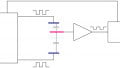
Consider the simple layout in Figure 1.
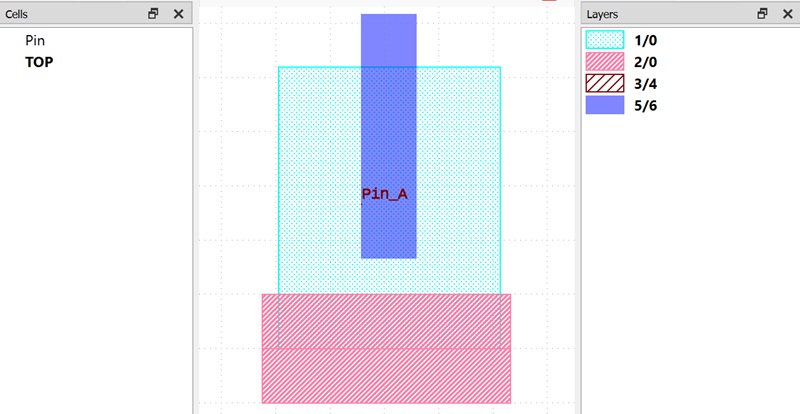
Figure 1. A simple layout for GDS.
EDA tools can easily convert layout drawings like this one into the GDSII file format. The open-source GDS2GDT utility can then convert the layout from the GDSII format to the GDT text format. A GDT version of the above layout is shown in Figure 2.
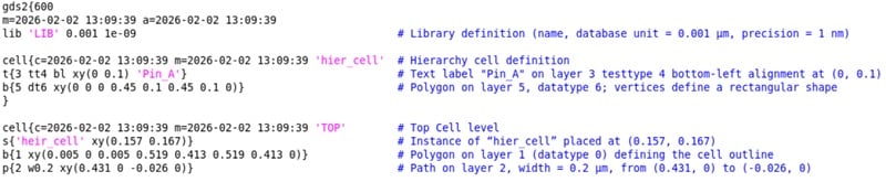
Figure 2. GDT version of Figure 1.
A human-readable text format for GDS is a lot more convenient. It allows you to parse and manipulate the layout with ease by editing the coordinate positions of polygons, paths, and block instances. It also means that a simple, straightforward text diff can be used when comparing two layouts.
GDS Manipulation With gdspy
Another way to automatically generate a cell library from an existing library is to use the gdspy Python library. This is an open-source library that allows you to generate and/or modify layouts with scripts. As mentioned at the beginning of this article, it's particularly handy when it comes to a flat, non-hierarchical layout library. You can find the official documentation for gdspy here.
To demonstrate, let's look at some code from the open-source ASAP7 cell library. The code in Table 1 is a simple example of how you can iterate through the cells to modify cell height.
Table 1. Code snippet for cell height scaling.
import numpy
import gdspy

height=0.270
NEW_height=0.300
scale_ratio=NEW_height/height

#open gds library
lib = gdspy.GdsLibrary(infile=InputGDS.gds)
The 7.5 M1 track cell is of 270 nm height. To increase the cell height to 300 nm, all the shapes need to be scaled in the Y-direction by a factor of 10/9.
If we scale the gate pitch, the width of some layers will be unchanged, while other layers are scaled by a uniform factor. The example script in Table 2 stretches the gate pitch of the ASAP 7.5 track library from 54 nm to 56 nm.
Table 2. Code snippet for gate scaling.
import numpy
import gdspy

InputGDS='layout.gds'
OutputGDS='newlayout.gds'
CPP=0.054
newCPP=0.056

#layers to be shifted and not scaled
LAYER= [[7], [17], [18], [88]]

#open gds library
lib = gdspy.GdsLibrary(infile=InputGDS)

#function to extract cell width from the boundary (layer# 100)
def get_cell_width(cell):

for polygon in cell.polygons:

if polygon.layers==[100]:
            bbox=polygon.get_bounding_box()
            return(bbox[1][0]-bbox[0][0])
Shapes in certain layers—gate, M1 metal, V1 VIA, and LISD, to give some examples—are only shifted, maintaining the widths. All other layers, including the N- and P-wells, fin region, and active region, are scaled by the factor 56/54. Figure 3 demonstrates the vertical and horizontal scaling for an inverter cell.
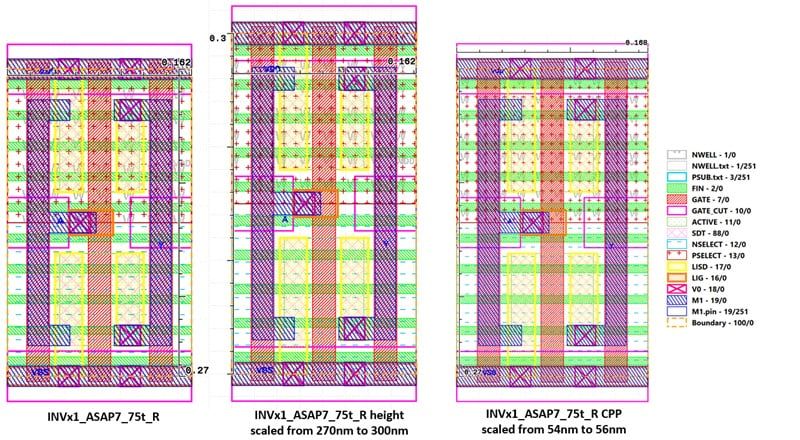
Figure 3. Original inverter layout (left), vertically scaled cell (center), and horizontally scaled cell (right).
Wrapping Up
For ultra-scaled nodes, rapid DTCO turnaround is essential. The layout-generation step is normally the bottleneck, so automating it is critical. In this article, we reviewed three different ways of accelerating the layout process.
It's worth noting that other practical approaches for automating layout modifications also exist, even if they are beyond the scope of our current discussion. Examples include SKILL scripts in Cadence Virtuoso and the Python API in KLayout.
All images used courtesy of Sandra Shaji
Related Content