 Facebook
 Google
 GitHub
 Linkedin
Understanding Anechoic Chambers for Electromagnetic and RF Testing
In this article, learn about anechoic chambers for electromagnetic measurement and testing, specifically for radio frequency (RF).
The word ‘anechoic’ means ‘without echo’. An anechoic chamber refers to a room that is designed to have minimal wave reflection from the walls, ceiling, and floor.
Electronics engineers use anechoic chambers for electromagnetic compatibility (EMC) or electromagnetic interference (EMI) and RF testing. The interior walls of these chambers are treated with special material to absorb electromagnetic waves.
There are also audio anechoic chambers, designed for applications such as audio recording, that absorb sound waves rather than electromagnetic energy.
This article touches on the basics of electromagnetic anechoic chambers, specifically how they pertain to RF testing.
Electromagnetic Measurement: A Common Requirement
Accurate measurement of electromagnetic waves is required in a wide range of application areas. For example, when employing an antenna, we need to know how the antenna sends the electromagnetic energy out into space (or receives it when used as a receiver). This is characterized by the radiation pattern of the antenna, as shown in Figure 1.
Figure 1(a) shows a dipole antenna created by two thin wires oriented along the z-axis.

Figure 1. Antenna model and patterns. Image used courtesy of Cisco
The figure also shows the 3-D radiation pattern (Figure 1(b)), as well as the principal plane patterns of the perfect dipole antenna (Figures 1(c) and 1(d)).
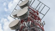
Antennas are an important part of a wireless communication system and affect many key decisions in the overall system design. For example, it’s important to understand the radiation pattern of cell towers to determine the spacing between them.
Measurement of electromagnetic waves is also required in areas such as electromagnetic compatibility tests and radar cross-section testing of missiles, aircraft, or other similar weapons.
Outdoor Electromagnetic Wave Measurement Challenges
An example setup to measure the radiation pattern of an antenna is shown in Figure 2.

Figure 2. An example setup for antenna radiation measurement
In this setup, the antenna under test (AUT) acts as a receiver.
A reference antenna transmits a known amount of power. The positioner rotates the AUT to the desired location (adjusts θ and φ) and the measurement system records the received power. These measurements form a polar plot of the radiation pattern in the azimuthal/elevation plane.
This measurement can be conducted in an open area test site (OATS); however, outdoor testing has a few disadvantages.
First, extraneous electromagnetic waves existing in the test environment will also be picked up by the AUT, introducing errors in our measurements. These extraneous waves can come from a variety of sources such as FM radio transmitters, cell phones, air traffic, and more.
Outdoor measurements of electromagnetic waves are also easily affected by weather conditions like wind and rain.
Another issue is the reflections from the floor and any other surrounding structures. As depicted in the above figure, these unwanted reflections will also be picked up by the AUT.
Anechoic Chambers as a Reliable RF Shielding Test Environment
One way to address the problems we've just discussed is to use anechoic chambers.
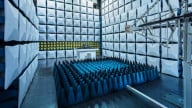
An anechoic chamber uses metal walls to shield our equipment from extraneous radio signals. To minimize the unwanted reflections, special RF absorbing materials, like the ones shown in Figure 3, are used to cover the interior walls of the chamber.

Figure 3. An example anechoic chamber for over the air (OTA) testing. Image used courtesy of Rohde and Schwarz
Shielding the test environment from outside interference along with minimal wave reflection off the walls, in effect simulates being inside an infinitely large room and enables accurate repeatable measurements.
Anechoic chambers can range in size from a tabletop enclosure to a typical room, where engineers can walk in and work, to a space as large as an aircraft hanger (Figure 4).

Figure 4. An example of a large anechoic chamber. Image used courtesy of Edwards Air Force Base and Christopher Okula
Large anechoic chambers can often cost an arm and a leg. An anechoic chamber that is large enough to provide a 10 m physical distance between the AUT and the transmit antenna can cost as much as $2 million.
RF Absorbing Materials for Anechoic Chambers
The inside surfaces of anechoic chambers are often covered with foam pyramids loaded with conductive carbon. The tapered structure of the pyramids transitions the radio waves from the air to the lossy carbon employed in the pyramids with minimal wave reflection.
The RF absorbers should absorb all of the incident electromagnetic energy and convert it to heat.
However, in practice, a portion of the incident RF power inevitably reflects off the chamber walls. The reflected wave is often about 0.1% to 1% of the incident wave, equivalent to an attenuation of -30 to -20 dB.
The new generation of broadband absorbers can offer better than −60-dB reflection coefficients for normal incidences at microwave frequencies.
The foam pyramids absorb upper-frequency electromagnetic waves, whereas lower frequencies are usually taken care of by ferrite tiles, which can be one of the most expensive components in a chamber.
Different Anechoic Chambers for Different Types of Measurements
As mentioned, anechoic chambers are used for a wide variety of measurements such as:
- Antenna pattern measurements
- Radiated emissions testing
- Radiated immunity testing
- Wireless transmitter (RF) testing
- Radar cross-section measurements
Different chambers might be required for each type of application.
For example, for transmitter/receiver testing, we might be interested in removing reflections from all surfaces, including the floor of the chamber, to simulate an environment with no multipath artifacts. In this case, we need a fully anechoic room (FAR) where all surfaces are covered with RF absorber material.
However, the preferred test facilities described in nearly all radiated and conducted emissions testing standards, including ANSI C63.4 and CISPR 16, are semi-anechoic chambers (SAC) and OATS.
While the walls and ceiling of a SAC are covered with RF absorber material, the floor is made of a metal reflecting ground plane.
One primary reason for using SAC in many EMC standards is that a reflective ground more closely simulates the real-world situation. In reality, the electromagnetic energy sent out by the device under test will be reflected off the ground to the nearby devices.
The chamber choice can also be affected by the type of standard you use for measurement.
For example, in automotive EMC testing, the employed EMC standard can affect the size of the test range and/or the placement of the anechoic absorber. Each standard has its own requirements and the engineers must ensure that the employed chamber complies with the standards of interest.
To see a complete list of my articles, please visit this page.


Why are semi-anechoic chambers widely used for EMC testing?