Facebook
 Google
 GitHub
 Linkedin
Use It Or Lose It? What Should You Do with Non-Functional Pads?
Circuit board stacks of four or more layers often have through vias that attach to pads on layers where there is no electrical connection. Should those non-function pads stay, or should they go? This article presents the problem and provides resources.
Circuit board stacks of four or more layers often have through vias that attach to pads on layers where there is no electrical connection. Should those non-function pads stay, or should they go? This article presents the problem and provides resources.
When creating a multiple-layer PCB, vias are created during manufacture to connect copper on different layers. Vias can pass through layers that they do not need to electrically connect to. So the question becomes, should you include a pad on those layers or not?
Sometimes, the decision is made for you at the fabrication house, where non-functioning pads are removed prior to manufacture. But the question still remains.
Should we retain non-functional via pads in our design or eliminate them?

A through-hole via for a 6-layer stack, with non-functional pads present (left) and removed (right)
The jury is still out but is leaning towards elimination. Before you decide for yourself, here's an overview and links to information on the subject.
The Case for Removing Non-Functional Pads
Drill Life
Printed circuit boards are composed of layers of copper and layers of substrate. In almost all instances, it is easier to drill through the substrate than to drill through copper. Many board houses will remove the non-functional pads to increase drill life, and the designer might never know. Why is drill life a concern? Worn or vibrating drill bits can create microfractures that later disrupt the plating process and create voids. To prevent this, drills must be monitored and replaced after a prescribed number of holes.

Electron micrograph showing wedge void between via barrel and copper layer. The right half of the image shows a vertical barrel wall with multiple cracks and voids. The left half of the image shows the via pad. Image used courtesy of courtesy Dr. Karl Dietz, DuPont.
Avoiding Problems at High Frequencies
High-speed circuits require that vias be as short as possible and not have any unnecessary copper stubs—these change the impedance of the signal transmission lines. A stub can also create problematic signal reflections. If the one-way propagation delay caused by the stub corresponds to one-fourth of the signal wavelength (or three-fourths, or five-fourths, and so on), the reflected signal will be delayed by half of a cycle. When the original waveform combines with the reflected waveform, the signal is lost (see this article for more information). Designers of very-high-frequency circuits will often remove non-functional pads and have the vias “back-drilled,” i.e., drilled from the other side (with a slightly larger bit) to remove the stub.
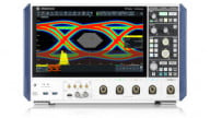
.jpg)
These eye diagrams indicate the potential improvement produced by a back-drilled via stub (left) compared to a via with the stub left in place (right). Image courtesy ti.com
1.jpg)
Back-drilled vias are shown on the lowest layer. Image used courtesy of Texas Instruments.
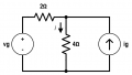
As mentioned above, non-functioning via pads (along with the antipad) take up valuable board space. This argues in favor of removing the unused pads.

In this example, the removal of non-functioning pads (left) allows the copper pour to fill more of the board than in the version where the non-functioning pads are kept.
If your PCB will be optically inspected prior to shipment, unused pads have another disadvantage: non-functional pads are optically inspected just like their functional counterparts. Removing the pads decreases inspection time.
The Case for Keeping Non-Functional Pads
Most substances expand when heated and contract when cooled, but different materials have different thermal conductivity and different coefficient of thermal expansion and, consequently, they don’t expand or contract in a uniform way. Furthermore, printed circuit boards have localized sources of heat, such as a linear voltage regulator that must dissipate a large amount of power.
.JPG)
This FLIR camera image of two PCBs from a previous AAC project show the thermal differences between two connected PCBs.
Manufacturers that do not remove non-functional pads do so for customer satisfaction or mechanical reasons. They believe that when the via shaft is bonded with as many layers as possible, it provides additional z-axis strength that resists the stresses of thermal expansion, which can cause cracks and separations in the via barrel.
.gif)
Image courtesy http://www.pwbcorp.com shows a via crack propagating during Z-axis expansion.
Resources
DFR Solutions surveyed multiple board fabrication houses and found that a majority of them remove non-functional pads. (Their research was the inspiration for this article.)
An article by PWB Interconnect Solutions, asserts that higher-aspect-ratio vias that are bonded to non-functional pads see a 10-30% reduction in long-term performance, and lower-aspect-ratio vias attached to non-functional pads see a 10-15% increase in long-term performance. (The aspect ratio is the ratio of the via’s length to its diameter.) Additionally, their research shows that failure typically happens at the innermost layers.
Conclusion
If this is the first time that you are hearing about this debate -- you can likely remove non-functioning pads to take advantage of the extra routing space. However, ensure that you have adequate spacing around the via in case the drill hole is several mils off of target. If you are designing boards that must work for years in environments that experience major fluctuations in temperature or humidity, you should consult with a reliability engineer for further advice.
Do you know more about this topic or have an opinion? We’d love to hear it -- please leave a comment below.