Facebook
 Google
 GitHub
 Linkedin
Using a Supervisory Circuit to Turn a Conventional SRAM into Fast Non-Volatile Memory
How can you build a fast non-volatile memory from a conventional SRAM? It turns out, you only need a back-up battery and some control circuitry.
In this article, we’ll see that a back-up battery along with some control circuitry can be used to build a fast non-volatile memory from a conventional SRAM.
The Need for a Fast Non-Volatile Memory
All memory types can be classified as volatile or non-volatile. Volatile memory loses its content when the device loses power while the non-volatile type can maintain the stored information even when power is removed.
The random access memory (RAM) family includes two important types—namely static RAM and dynamic RAM—that are both volatile. Two non-volatile memory examples that are widely used in embedded systems are EEPROM and Flash.
Although EEPROM and Flash memories have the advantage of being non-volatile, they have significantly longer write cycles compared to a RAM chip. For example, the write cycle of a typical EEPROM is in the range of 1–10 ms while the access time of a typical SRAM can be around 70 ns (fast SRAMs offer access times in the range of 10 ns, according to Cypress Semiconductor).
Having a write cycle much longer than a read cycle makes EEPROM and Flash memories suited for applications in which the number of memory read operations is much more than the required number of write operations.
On the other hand, there are applications such as point-of-sale (POS) terminals, network processing engines, and servers where non-volatile memory with fast read and write cycles are required. In these cases, we can use a conventional SRAM memory along with a back-up battery and some control circuitry to create a fast non-volatile memory.
These non-volatile memories are often referred to as battery-backed SRAMs.
Battery-Backed SRAM
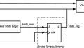
A battery-backed SRAM (BBSRAM) incorporates a battery as an alternative source of power to retain the memory content during power failure. The basic idea is illustrated in Figure 1.

Figure 1. BBSRAMs retain a device's memory in the case of a power failure.
The main power supply (Vcc) and the battery are applied to a supervisory chip that monitors Vcc for an out-of-tolerance condition. During a normal mode of operation, Vcc appears at the output of the supervisory chip (Vout) to supply power to the SRAM. However, in the event of a power failure, the battery is used to power the SRAM.
The following timing diagram illustrates the operation of the TPS3617, which is a supervisory chip for 5-V supplies.

Figure 2. Timing diagram of the TPS3617. Image used courtesy of Texas Instruments
When Vcc drops below a factory-trimmed threshold (4.55 V for TPS3617), the output Vout switches from Vcc to VBAT.
Data Retention of a BBSRAM
Data retention is the maximum period of time that a non-volatile device can maintain its content. With a BBSRAM, data retention is mainly determined by the battery lifetime. To maximize the battery lifetime, we need to draw as little current as possible in the battery mode of operation.
As shown in Figure 1, we can use the supervisory chip to control the chip-enable input of the SRAM, $$\frac{}{CE_{RAM}}$$, and put it in standby mode when required. Note that SRAMs need to draw only a small leakage current (less than about 10 μA) to retain the data at standby mode.
During a normal mode of operation, the supervisory chip passes all transitions of $$\frac{}{CE_{IN}}$$, which is controlled by the microcontroller, to $$\frac{}{CE_{OUT}}$$. Hence, normally, the supervisory chip is transparent and the MCU can enable/disable the SRAM. However, during a power failure, the supervisory chip sets $$\frac{}{CE_{RAM}}$$ to logic high to put the SRAM in the standby mode.
This is illustrated in Figure 3.
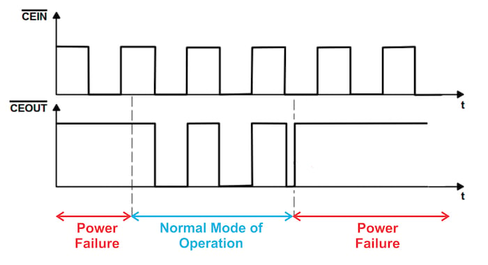
Figure 3. In the event of power failure, the SRAM is put in standby mode when the supervisory chip sets $$\frac{}{CE_{RAM}}$$ to logic high. Image (modified) used courtesy of Texas Instruments
Putting the SRAM in standby mode minimizes the power consumption in the battery mode. In this way, a typical BBSRAM can have a data retention of about 10 years.
It is worthwhile to mention that the battery lifetime can be affected by a mechanism other than the memory standby current consumption—that is, the battery electrolyte loss through the crimp seal. The loss rate of the electrolyte accelerates at elevated temperatures.
For example, at 85°C, the battery will completely deplete in about two years even if it is not at all connected to a load. Therefore, we need to take into account the battery capacity, the memory current requirements, and the ambient temperature to have a realistic prediction of the battery lifetime.
Avoiding Erroneous Write Cycles
We discussed above that disabling the SRAM increases the battery lifetime and consequently, data retention of a BBSRAM. Putting the SRAM in standby mode is also required to avoid erroneous write cycles.
In Figure 1, you'll notice that the MCU is operated by the main power supply VCC. An out-of-tolerance condition on VCC can lead to an unpredictable value at the MCU outputs. If a power failure occurs and the SRAM is not disabled, the MCU might write erroneous data to the SRAM. Therefore, we need to write-protect the SRAM by putting it in standby mode when a power failure is detected.
Note that many supervisory chips control their chip-enable output $$\frac{}{CE_{OUT}}$$ in a slightly different manner from that depicted in Figure 3.
For example, Figure 4 shows how the TPS3610 controls the SRAM chip enable.

Figure 4. Chip-enable timing of the TPS3610. Image (adapted) used courtesy of Texas Instruments
As you can see, the second power failure in the figure above occurs while $$\frac{}{CE_{IN}}$$ is logic low (the MCU has enabled the SRAM). In this case, the TPS3610 puts the SRAM into standby mode after a delay of 15 μs. This delay is implemented to allow a current potential write cycle to complete.
Supervisory chips from different manufacturers usually incorporate this delay; however, the value of the delay should be checked with the datasheet and can vary from about 10 μs to 15 μs.
Battery-Backed SRAM Chips
As discussed above, we can use a supervisory chip along with a battery to make an SRAM behave like a non-volatile SRAM. Alternatively, we can use a BBSRAM chip such as DS1225 that offers all of the required elements (the lithium power source, the control circuitry, and the SRAM) in a single package.
The device monitors the power supply for any out-of-tolerance condition. In the event of a power failure, it automatically uses the integrated battery to power the SRAM and puts the memory in standby mode to protect it from data corruption. The device package matches that of existing SRAMs, which makes upgrading the current memory to a non-volatile type very easy.
Conclusion
There are applications such as point-of-sale (POS) terminals, network processing engines, and servers in which non-volatile memory with fast read and write cycles are required. In these cases, we can use a conventional SRAM memory along with a back-up battery and some control circuitry to create a fast non-volatile memory.
An alternative solution is the use of an EEPROM as back-up memory to store the SRAM information during a power failure. The next article in this series will introduce the EEPROM-based method and compare it with a BBSRAM.
To see a complete list of my articles, please visit this page.
Related Content