 Facebook
 Google
 GitHub
 Linkedin
The Fundamentals of Wi-Fi Antennas
Amateur radio operators ("hams") have long said, "If you want a bigger signal, put up more metal and put it up higher." Antennas for Wi-Fi are no exception.
Wi-Fi communications depend on radio-frequency energy that is transmitted and received over antennas. Better antennas will produce better coverage, and choosing the right antenna is easy if you understand the fundamentals.
Antennas in General
Although the subject of this series of articles is antennas specifically for Wi-Fi use, some background information about antennas in general will be helpful. This is the first in a series.
An antenna is a device that radiates radio waves when supplied with electric power, and/or a device that converts radio waves into electric power. Antennas are sometimes intentionally created to be antennas (like the antenna on a wireless router) and are sometimes created for another purpose (like the wires on your earbuds,) but also incidentally function as an antenna.
.png)
Antennas are always directional--that is, they transmit and/or receive radio waves better in some directions than in other directions. Antennas that are not intended to be directional are called “omnidirectional” or “nondirectional,” even though they are never perfectly nondirectional.
Wavelength, Frequency, and Antenna Length
Radio waves, like all waves in the electromagnetic spectrum, are measured in frequency, and the basic unit of frequency is the Hertz (abbreviated Hz,) which is one cycle per second. Hertz is used in honor of Heinrich Rudolf Hertz, the first person to prove the existence of electromagnetic waves. The basic Hertz unit is often preceded with a multiplier such as kilo (1,000) or mega (1,000,000) or giga (1,000,000,000.)
In addition to Hertz, which is a unit of frequency, radio waves are sometimes referred to in terms of their length by using the term “wavelength.” As you likely realize, the terms Hertz and wavelength are mathematically related, and the formula below is commonly used to define that relationship.
wavelength (in meters) = 300 / frequency (in MHz)
For example, a frequency of 14.300 MHz has a wavelength of 20.979 meters. This relationship between frequency and wavelength is especially important to antenna design because the wavelength of a frequency is used to calculate many of the dimensions of an antenna’s design.
Dipole Antennas
One of the simplest antennas is called a “half-wave dipole,” is a total of ½ wavelength long, and is constructed of two halves, each of which is ¼ wavelength long. Each of the two halves is fed by a separate conductor in the feedline.
For the same 14.300 MHz frequency as previously mentioned, a dipole would theoretically be 10.4895 ( ½ of 20.979) meters from end to end, and would consist of two elements, each 5.24476 meters long. Note, however, that antennas are not always constructed exactly according to the calculated theoretical dimensions.
The photos below show a much smaller (homemade) dipole for short range digital television reception, and demonstrate the simplicity that all dipoles share regardless of their operating frequency.


The radiators are made from steel wire cut from a common coat hanger and connected to the coaxial transmission line with steel nuts and bolts. A small piece of perfboard is the center insulator and the structural base for the assembly. And yes, despite the antenna’s crude construction, it does receive HDTV signals from stations up to 20 miles away while hung on the back of the television four feet off the ground. (You should be able to calculate the operating frequency from the information given in this article.)
Antenna Polarization
The orientation of an antenna with respect to the earth's surface is called its "polarization." Those that are intended for their radio waves to be oriented primarily parallel to the earth's surface are said to be "horizontal," and those that are intended for their radio waves to be oriented primarily at a right angle to the earth's surface are said to be "vertical."
Some antennas, like the dipole pictured above, can be used in either polarization simply by changing the position. In the orientation shown above, the dipole's element is parallel to the earth's surface, and therefore the antenna is horizontally polarized. Reorienting the dipole so that its element tips point up and down makes it vertically polarized.
The factors involved for choosing one polarization over another include operating frequency, desired coverage, mechanical constraints, and customary practice. A very important consideration is that all antennas within a communication system should use the same polarization. When there is a mix of polarizations within a system, or when the polarization of some antennas is unknown, circular polarization is sometimes used to maximize compatibility. Wi-Fi antennas are almost always vertically polarized.
Antenna Gain
As previously stated, antennas transmit (and receive) radio waves better in certain directions, thereby increasing the effective radiated power (ERP) in those directions. Note that the total radiated power is not increased, but is merely stronger in one or more directions, and is weaker in other directions. Even a simple horizontal dipole has gain in two directions: parallel to its radiators on both the “front” and “back” sides.
This increase in ERP is called “gain,” and applies to both transmitted and received signals. The unit of measurement most often used to quantify gain is the decibel, or dB, which is based on the Bel, which was named in honor of Alexander Graham Bell. If you want to understand how to calculate Bels and decibels, you are on your own since that is outside the scope of this article. Suffice it to say that the higher the dB rating of an antenna, the more gain it supposedly has.
In addition to the dB, there is another unit that is used to describe antenna gain: the dBi, or decibel isotropic. An isotropic source is a theoretical antenna that consists of a single point that radiates RF in every direction, like a sphere. The dBi is more commonly used to quantify antenna gain for one reason: a dBi rating results in higher numbers than the dB rating, which makes an antenna seem to have more gain, even though it does not actually have more gain.
As before, the exact methods for calculating dBi are not essential to this discussion. Just remember this: higher dB or dBi ratings indicate higher gain, and if you are comparing antennas, be sure that they are rated using the same unit of measure — either dB or dBi — but not a mixture of the two.
Wi-Fi Frequencies
There are five different bands used for Wi-Fi transmissions: 2.4GHz, 3.6GHz, 4.9GHz, 5GHz, and 5.9GHz. How the bands are used varies from one country to another. The most widely used is the 2.4GHz band and will be the focus of this article, but the general principles are applicable to all bands.
The 2.4GHz band extends from approximately 2.4GHz to 2.5GHz; thus, the approximate center of the band is 2.45GHz, and is the frequency that will be used for the calculations that follow.
The formula presented above
wavelength (in meters) = 300 / frequency (in MHz)
can be conveniently converted to the following.
wavelength (in millimeters) = 300 / frequency (in GHz)
Thus, the wavelength of a 2.45GHz signal is 122.45 mm. A dipole at 2.45GHz is 61.22 mm from end to end, and each of the two halves is 30.61 mm. For those of you who are accustomed to working in inches, a dipole at 2.45GHz is 2.41” from end to end, and each of the two halves is 1.205”. No matter which units you use, the elements are quite small in the 2.4GHz band, and even smaller in the other four bands.
Wi-Fi Dipole
The photograph below shows two Wi-Fi antennas that were removed from a 2.4GHz wireless router. The bottom antenna remains in its plastic cover and retains the hinged base that allows for it to be oriented vertically regardless of the mounting position of the router. The top antenna has been removed from its plastic cover to reveal the internal construction.
Although it may not be immediately evident, the antenna is a dipole. One half of the dipole is the white wire that protrudes to the left, and the other half of the dipole is the metal cylinder. Each half is electrically insulated from the other, and is approximately ¼ wavelength long. Similar antennas have a gain of about 2dBi, and exhibit a relatively circular radiation pattern.
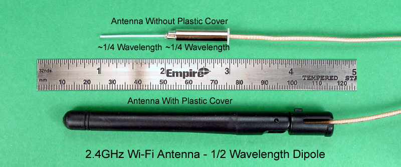
In both cases, the wire feedline exits from the bottom of the antenna to connect to the Wi-Fi radio transceiver. The feedline is a coaxial cable with an inner conductor and an outer braided shield; a clear plastic cover encases the feedline. This particular feedline is often used for Wi-Fi devices because of its small size and relatively low RF losses; it is designated RG-178. Coaxial feedlines are often referred to as "coax."
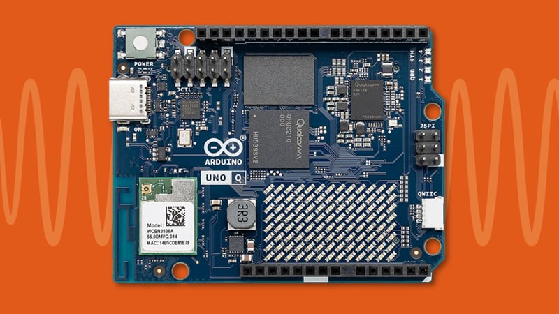
The other end of the coax is connected the router, as shown below. Note that the shields are securely soldered to the ground plane on the PCB, and the center conductors are soldered to PCB tracks that lead to the transceiver inside the gold metal box. The inset shows an alternative soldering style; sometimes connectors are soldered to the PCB and the coax is equipped with mating connectors that snap into place.
.png)
Coming Up
At this point, you should have an understanding of antenna fundamentals as they apply to Wi-Fi. Future articles in this series will focus on nondirectional as well as directional antennas for Wi-Fi use. Both commercially available and homebrew antennas will be discussed, and guidelines will be provided for you to construct, expand, and improve your Wi-Fi network.


Very interesting!
Can I save these kind of articles in a bookmark list or a read later list?