 Facebook
 Google
 GitHub
 Linkedin
Three-phase Power Systems
What is Split-Phase Power Systems?
Split-phase power systems achieve their high conductor efficiency and low safety risk by splitting up the total voltage into lesser parts and powering multiple loads at those lesser voltages while drawing currents at levels typical of a full-voltage system.
This technique, by the way, works just as well for DC power systems as it does for single-phase AC systems. Such systems are usually referred to as three-wire systems rather than split-phase because “phase” is a concept restricted to AC.
But we know from our experience with vectors and complex numbers that AC voltages don’t always add up as we think they would if they are out of phase with each other.
This principle, applied to power systems, can be put to use to make power systems with even greater conductor efficiencies and lower shock hazard than with split-phase.
Examples
Two 120° Out of Phase Voltage Sources
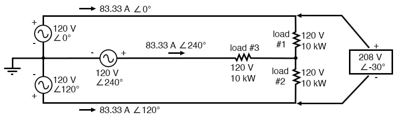
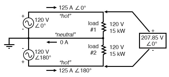
Suppose that we had two sources of AC voltage connected in series just like the split-phase system we saw before, except that each voltage source was 120° out of phase with the other: (Figure below)
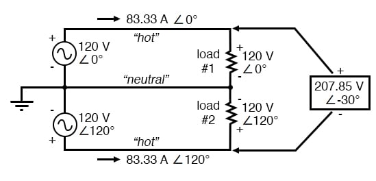
Pair of 120 Vac sources phased 120°, similar to split-phase.
Since each voltage source is 120 volts, and each load resistor is connected directly in parallel with its respective source, the voltage across each load must be 120 volts as well. Given load currents of 83.33 amps, each load must still be dissipating 10 kilowatts of power.
However, voltage between the two “hot” wires is not 240 volts (120 ∠ 0° - 120 ∠ 180°) because the phase difference between the two sources is not 180°. Instead, the voltage is:
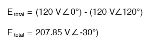
Nominally, we say that the voltage between “hot” conductors is 208 volts (rounding up), and thus the power system voltage is designated as 120/208.
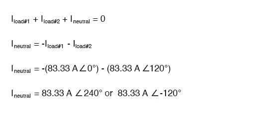
If we calculate the current through the “neutral” conductor, we find that it is not zero, even with balanced load resistances. Kirchhoff’s Current Law tells us that the currents entering and exiting the node between the two loads must be zero: (Figure below)
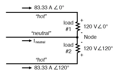
Neutral wire carries a current in the case of a pair of 120° phased sources.
Findings and Conclusions
So, we find that the “neutral” wire is carrying a full 83.33 amps, just like each “hot” wire.
Note that we are still conveying 20 kW of total power to the two loads, with each load’s “hot” wire carrying 83.33 amps as before.
With the same amount of current through each “hot” wire, we must use the same gauge copper conductors, so we haven’t reduced system cost over the split-phase 120/240 system.
However, we have realized a gain in safety, because the overall voltage between the two “hot” conductors is 32 volts lower than it was in the split-phase system (208 volts instead of 240 volts).
Three 120° Out of Phase Voltage Sources
The fact that the neutral wire is carrying 83.33 amps of current raises an interesting possibility: since it's carrying current anyway, why not use that third wire as another “hot” conductor, powering another load resistor with a third 120 volt source having a phase angle of 240°?
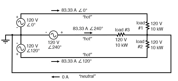
That way, we could transmit more power (another 10 kW) without having to add any more conductors. Let’s see how this might look: (Figure below)
With a third load phased 120° to the other two, the currents are the same as for two loads.
SPICE Calculations for Three-phase System
A full mathematical analysis of all the voltages and currents in this circuit would necessitate the use of a network theorem, the easiest being the Superposition Theorem.
I’ll spare you the long, drawn-out calculations because you should be able to intuitively understand that the three voltage sources at three different phase angles will deliver 120 volts each to a balanced triad of load resistors.
For proof of this, we can use SPICE to do the math for us: (Figure below, SPICE listing: 120/208 polyphase power system)
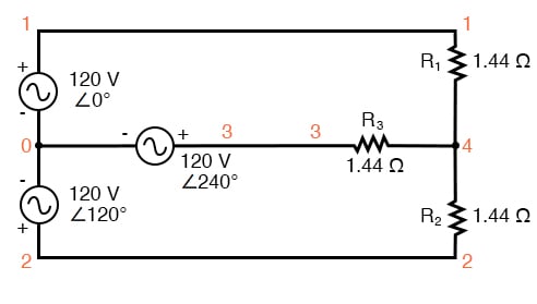
SPICE circuit: Three 3-Φ loads phased at 120°.
120/208 polyphase power system v1 1 0 ac 120 0 sin v2 2 0 ac 120 120 sin v3 3 0 ac 120 240 sin r1 1 4 1.44 r2 2 4 1.44 r3 3 4 1.44 .ac lin 1 60 60 .print ac v(1,4) v(2,4) v(3,4) .print ac v(1,2) v(2,3) v(3,1) .print ac i(v1) i(v2) i(v3) .end
VOLTAGE ACROSS EACH LOAD freq v(1,4) v(2,4) v(3,4) 6.000E+01 1.200E+02 1.200E+02 1.200E+02 VOLTAGE BETWEEN “HOT” CONDUCTORS freq v(1,2) v(2,3) v(3,1) 6.000E+01 2.078E+02 2.078E+02 2.078E+02 CURRENT THROUGH EACH VOLTAGE SOURCE freq i(v1) i(v2) i(v3) 6.000E+01 8.333E+01 8.333E+01 8.333E+01
Sure enough, we get 120 volts across each load resistor, with (approximately) 208 volts between any two “hot” conductors and conductor currents equal to 83.33 amps. (Figure below)
At that current and voltage, each load will be dissipating 10 kW of power.
Notice that this circuit has no “neutral” conductor to ensure stable voltage to all loads if one should open.
What we have here is a situation similar to our split-phase power circuit with no “neutral” conductor: if one load should happen to fail open, the voltage drops across the remaining load(s) will change.
To ensure load voltage stability in the event of another load opening, we need a neutral wire to connect the source node and load node together:
SPICE circuit annotated with simulation results: Three 3-Φ loads phased at 120°.
So long as the loads remain balanced (equal resistance, equal currents), the neutral wire will not have to carry any current at all. It is there just in case one or more load resistors should fail open (or be shut off through a disconnecting switch).
Polyphase Circuit
This circuit we’ve been analyzing with three voltage sources is called a polyphase circuit. The prefix “poly” simply means “more than one,” as in “polytheism” (belief in more than one deity), “polygon” (a geometrical shape made of multiple line segments: for example, pentagon and hexagon), and “polyatomic” (a substance composed of multiple types of atoms).
Since the voltage sources are all at different phase angles (in this case, three different phase angles), this is a “polyphase” circuit.
More specifically, it is a three-phase circuit, the kind used predominantly in large power distribution systems.
Three-Phase System versus Single-Phase System
Single-Phase System
Let’s survey the advantages of a three-phase power system over a single-phase system of equivalent load voltage and power capacity. A single-phase system with three loads connected directly in parallel would have a very high total current (83.33 times 3, or 250 amps. (Figure below)
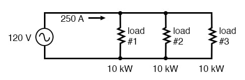
For comparison, three 10 Kw loads on a 120 Vac system draw 250 A.
This would necessitate 3/0 gage copper wire (very large!), at about 510 pounds per thousand feet, and with a considerable price tag attached. If the distance from source to load was 1000 feet, we would need over a half-ton of copper wire to do the job.
Split-phase System
On the other hand, we could build a split-phase system with two 15 kW, 120 volt loads. (Figure below)
Split phase system draws half the current of 125 A at 240 Vac compared to 120 Vac system.
Our current is half of what it was with the simple parallel circuit, which is a great improvement.
We could get away with using number 2 gauge copper wire at a total mass of about 600 pounds, figuring about 200 pounds per thousand feet with three runs of 1000 feet each between source and loads. However, we also have to consider the increased safety hazard of having 240 volts present in the system, even though each load only receives 120 volts.
Overall, there is greater potential for a dangerous electric shock to occur.
Three-Phase System
When we contrast these two examples against our three-phase system (Figure above), the advantages are quite clear.
First, the conductor currents are quite a bit less (83.33 amps versus 125 or 250 amps), permitting the use of much thinner and lighter wire. We can use number 4 gauge wire at about 125 pounds per thousand feet, which will total 500 pounds (four runs of 1000 feet each) for our example circuit.
This represents significant cost savings over the split-phase system, with the additional benefit that the maximum voltage in the system is lower (208 versus 240).
One question remains to be answered: how in the world do we get three AC voltage sources whose phase angles are exactly 120° apart?
Obviously we can’t center-tap a transformer or alternator winding like we did in the split-phase system, since that can only give us voltage waveforms that are either in phase or 180° out of phase.
Perhaps we could figure out some way to use capacitors and inductors to create phase shifts of 120°, but then those phase shifts would depend on the phase angles of our load impedances as well (substituting a capacitive or inductive load for a resistive load would change everything!).
The best way to get the phase shifts we’re looking for is to generate it at the source: construct the AC generator (alternator) providing the power in such a way that the rotating magnetic field passes by three sets of wire windings, each set spaced 120° apart around the circumference of the machine as in Figure below.
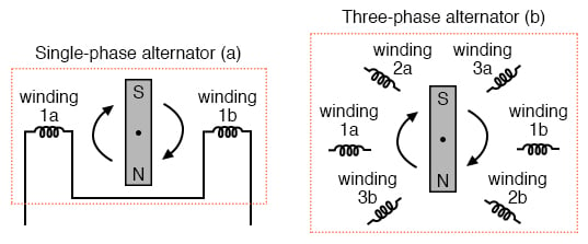
(a) Single-phase alternator, (b) Three-phase alternator.
Together, the six “pole” windings of a three-phase alternator are connected to comprise three winding pairs, each pair producing AC voltage with a phase angle 120° shifted from either of the other two winding pairs.
The interconnections between pairs of windings (as shown for the single-phase alternator: the jumper wire between windings 1a and 1b) have been omitted from the three-phase alternator drawing for simplicity.
In our example circuit, we showed the three voltage sources connected together in a “Y” configuration (sometimes called the “star” configuration), with one lead of each source tied to a common point (the node where we attached the “neutral” conductor).
The common way to depict this connection scheme is to draw the windings in the shape of a “Y” like Figure below.
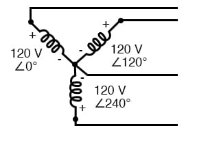
Alternator “Y” configuration.
The “Y” configuration is not the only option open to us, but it is probably the easiest to understand at first. More to come on this subject later in the chapter.
REVIEW:
- A single-phase power system is one where there is only one AC voltage source (one source voltage waveform).
- A split-phase power system is one where there are two voltage sources, 180° phase-shifted from each other, powering a two series-connected loads. The advantage of this is the ability to have lower conductor currents while maintaining low load voltages for safety reasons.
- A polyphase power system uses multiple voltage sources at different phase angles from each other (many “phases” of voltage waveforms at work). A polyphase power system can deliver more power at less voltage with smaller-gage conductors than single- or split-phase systems.
- The phase-shifted voltage sources necessary for a polyphase power system are created in alternators with multiple sets of wire windings. These winding sets are spaced around the circumference of the rotor’s rotation at the desired angle(s).
RELATED WORKSHEETS:


Can anyone explain why 208V(207.85V) in the two 120 degree out of phase voltage sources example
And
The 208V in the three (120 degree) out of phase example
Are -30 degrees?
I’m trying to figure out the math in both examples to understand and have asked several other people who didn’t know why either.
To answer bregGoz’s question, negative 120V at 120 degrees is the same as positive 120V at -60 degrees (subtracting 180 degrees flips the sign). This means we’re adding two voltages, -60 degrees out of phase but with the same magnitude, which means the resulting phase will be in the middle at -30 degrees.