 Facebook
 Google
 GitHub
 Linkedin
Single-phase Induction Motors
What's one way to solve the single phase problem?
Build a 2-phase motor, deriving 2-phase power from single phase.
A three-phase motor may be run from a single-phase power source. However, it will not self-start. It may be hand started in either direction, coming up to speed in a few seconds. It will only develop 2/3 of the 3-φ power rating because one winding is not used.

3-φ motor runs from 1-φ power but does not start
Single Coil of a Single Phase Motor
The single coil of a single-phase induction motor does not produce a rotating magnetic field, but a pulsating field reaching maximum intensity at 0° and 180° electrical.

Single-phase stator produces a nonrotating, pulsating magnetic field
Another view is that the single-coil excited by a single-phase current produces two counter-rotating magnetic field phasors, coinciding twice per revolution at 0° (Figure above-a) and 180° (figure e). When the phasors rotate to 90° and -90° they cancel in figure c.
At 45° and -45° (figure b) they are partially additive along the +x axis and cancel along the y-axis. An analogous situation exists in figure d. The sum of these two phasors is a phasor stationary in space, but alternating polarity in time. Thus, no starting torque is developed.
However, if the rotor is rotated forward at a bit less than the synchronous speed, It will develop maximum torque at 10% slip with respect to the forward rotating phasor. Less torque will be developed above or below 10% slip.
The rotor will see 200% - 10% slip with respect to the counter-rotating magnetic field phasor. Little torque (see torque vs slip curve) other than a double frequency ripple is developed from the counter-rotating phasor. Thus, the single-phase coil will develop torque, once the rotor is started.
If the rotor is started in the reverse direction, it will develop a similar large torque as it nears the speed of the backward rotating phasor.
Single-phase induction motors have a copper or aluminum squirrel cage embedded in a cylinder of steel laminations, typical of polyphase induction motors.
Permanent-Split Capacitor Motor
One way to solve the single phase problem is to build a 2-phase motor, deriving 2-phase power from single phase. This requires a motor with two windings spaced apart 90° electrical, fed with two phases of current displaced 90° in time. This is called a permanent-split capacitor motor.

Permanent-split capacitor induction motor
This type of motor suffers increased current magnitude and backward time shift as the motor comes up to speed, with torque pulsations at full speed. The solution is to keep the capacitor (impedance) small to minimize losses.
The losses are less than for a shaded pole motor. This motor configuration works well up to 1/4 horsepower (200 watts), though, usually applied to smaller motors. The direction of the motor is easily reversed by switching the capacitor in series with the other winding. This type of motor can be adapted for use as a servo motor, described elsewhere in this chapter.

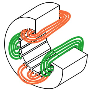
Single-phase induction motor with embedded stator coils
Single-phase induction motors may have coils embedded into the stator for larger size motors. Though, the smaller sizes use less complex to build concentrated windings with salient poles.
Capacitor-Start Induction Motor
In the figure below a larger capacitor may be used to start a single-phase induction motor via the auxiliary winding if it is switched out by a centrifugal switch once the motor is up to speed. Moreover, the auxiliary winding may be many more turns of heavier wire than used in a resistance split-phase motor to mitigate excessive temperature rise.
The result is that more starting torque is available for heavy loads like air conditioning compressors. This motor configuration works so well that it is available in multi-horsepower (multi-kilowatt) sizes.

Capacitor-start induction motor
Capacitor-Run Motor Induction Motor
A variation of the capacitor-start motor (figure below) is to start the motor with a relatively large capacitor for high starting torque, but leave a smaller value capacitor in place after starting to improve running characteristics while not drawing excessive current. The additional complexity of the capacitor-run motor is justified for larger size motors.

Capacitor-run motor induction motor
A motor starting capacitor may be a double-anode non-polar electrolytic capacitor which could be two + to + (or - to -) series-connected polarized electrolytic capacitors. Such AC rated electrolytic capacitors have such high losses that they can only be used for intermittent duty (1 second on, 60 seconds off) like motor starting.
A capacitor for motor running must not be of electrolytic construction, but a lower loss polymer type.
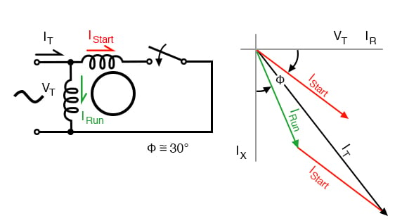
Resistance Split-Phase Motor Induction Motor
If an auxiliary winding of much fewer turns, a smaller wire is placed at 90°electrical to the main winding, it can start a single-phase induction motor. With lower inductance and higher resistance, the current will experience less phase shift than the main winding.
About 30° of phase difference may be obtained. This coil produces a moderate starting torque, which is disconnected by a centrifugal switch at 3/4 of synchronous speed. This simple (no capacitor) arrangement serves well for motors up to 1/3 horsepower (250 watts) driving easily started loads.
Resistance split-phase motor induction motor
This motor has more starting torque than a shaded pole motor (next section), but not as much as a two-phase motor built from the same parts. The current density in the auxiliary winding is so high during starting that the consequent rapid temperature rise precludes frequent restarting or slow starting loads.
Nola Power Factor Corrector
Frank Nola of NASA proposed a power factor corrector for improving the efficiency of AC induction motors in the mid-1970s. It is based on the premise that induction motors are inefficient at less than full load. This inefficiency correlates with a low power factor.
The less than unity power factor is due to magnetizing current required by the stator. This fixed current is a larger proportion of total motor current as the motor load is decreased. At light load, the full magnetizing current is not required. It could be reduced by decreasing the applied voltage, improving the power factor and efficiency.
The power factor corrector senses power factor, and decreases motor voltage, thus restoring a higher power factor and decreasing losses.
Since single-phase motors are about 2 to 4 times as inefficient as three-phase motors, there are potential energy savings for 1-φ motors. There are no savings for a fully-loaded motor since all the stator magnetizing current is required.
The voltage cannot be reduced. But there are potential savings from a less than fully loaded motor. A nominal 117 VAC motor is designed to work at as high as 127 VAC, as low as 104 VAC. That means that it is not fully loaded when operated at greater than 104 VAC, for example, a 117 VAC refrigerator.
It is safe for the power factor controller to lower the line voltage to 104-110 VAC. The higher the initial line voltage, the greater the potential savings. Of course, if the power company delivers closer to 110 VAC, the motor will operate more efficiently without any add-on device.
Any substantially idle, 25% FLC or less, a single-phase induction motor is a candidate for a PFC. Though, it needs to operate a large number of hours per year. And the more time it idles, as in lumber saw, punch press, or conveyor, the greater the possibility of paying for the controller in a few years operation.
It should be easier to pay for it by a factor of three as compared to the more efficient 3-φ-motor. The cost of a PFC cannot be recovered for a motor operating only a few hours per day.
Summary: Single-phase induction motors
- Single-phase induction motors are not self-starting without an auxiliary stator winding driven by an out of phase current of near 90°. Once started the auxiliary winding is optional.
- The auxiliary winding of a permanent split capacitor motor has a capacitor in series with it during starting and running.
- A capacitor-start induction motor only has a capacitor in series with the auxiliary winding during starting.
- A capacitor-run motor typically has a large non-polarized electrolytic capacitor in series with the auxiliary winding for starting, then a smaller non-electrolytic capacitor during running.
- The auxiliary winding of a resistance split-phase motor develops a phase difference versus the main winding during starting by virtue of the difference in resistance.
RELATED WORKSHEET:


For the permanent-split capacitor motor, it current says “This requires a motor with two windings spaced apart 90° electrical”. When referring to ‘physical’ angle of windings, should it actually be considered as two windings spaced 90° apart physically? Not electrically. So the two windings should be physically spaced 90° apart (relative to each other in terms of their axes). And then, later, the ‘electrical’ AC voltages applied across each coil are purposely made to be 90° apart .... electrically 90° degrees apart. So this means that the coils are 90° apart physically, and the applied voltages (a separate consideration) are 90° apart electrically, which is unrelated to the windings being 90° apart physically.
Very good post. I really like it. To read this type of Post In Hindi
Visit this Website..
https://hindi.electricaldiary.com/2020/05/single-phase-induction-motor.html