 Facebook
 Google
 GitHub
 Linkedin
AC Inductor Circuits
Resistors vs. Inductors
Inductors do not behave the same way as resistors do. Whereas resistors simply oppose the flow of current through them (by dropping a voltage directly proportional to the current), inductors oppose changes in current through them, by dropping a voltage directly proportional to the rate of change of current.
In accordance with Lenz’s Law, this induced voltage is always of such a polarity as to try to maintain current at its present value. That is, if the current is increasing in magnitude, the induced voltage will “push against” the current flow; if the current is decreasing, the polarity will reverse and “push with” the current to oppose the decrease.
This opposition to current change is called reactance, rather than resistance. Expressed mathematically, the relationship between the voltage dropped across the inductor and rate of current change through the inductor is as such:

Alternating Current in a Simple Inductive Circuit
The expression di/dt is one from calculus, meaning the rate of change of instantaneous current (i) over time, in amps per second.
The inductance (L) is in Henrys, and the instantaneous voltage (e), of course, is in volts. Sometimes you will find the rate of instantaneous voltage expressed as “v” instead of “e” (v = L di/dt), but it means the exact same thing.
To show what happens with alternating current, let’s analyze a simple inductor circuit:
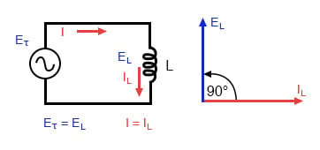
Pure inductive circuit: Inductor current lags inductor voltage by 90°.
If we were to plot the current and voltage for this very simple circuit, it would look something like this:
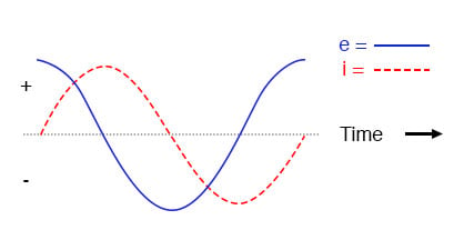
Pure inductive circuit, waveforms.
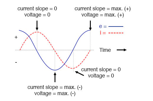
Remember, the voltage dropped across an inductor is a reaction against the change in current through it.
Therefore, the instantaneous voltage is zero whenever the instantaneous current is at a peak (zero change, or level slope, on the current sine wave), and the instantaneous voltage is at a peak wherever the instantaneous current is at maximum change (the points of steepest slope on the current wave, where it crosses the zero line).
This results in a voltage wave that is 90° out of phase with the current wave. Looking at the graph, the voltage wave seems to have a “head start” on the current wave; the voltage “leads” the current and the current “lags” behind the voltage.
Current lags voltage by 90° in a pure inductive circuit.
Things get even more interesting when we plot the power for this circuit:
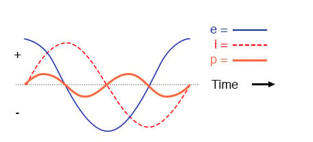
In a pure inductive circuit, instantaneous power may be positive or negative.
Because instantaneous power is the product of the instantaneous voltage and the instantaneous current (p=ie), the power equals zero whenever the instantaneous current or voltage is zero. Whenever the instantaneous current and voltage are both positive (above the line), the power is positive.
As with the resistor example, the power is also positive when the instantaneous current and voltage are both negative (below the line).
However, because the current and voltage waves are 90° out of phase, there are times when one is positive while the other is negative, resulting in equally frequent occurrences of negative instantaneous power.
What is Negative Power?
But what does negative power mean? It means that the inductor is releasing power back to the circuit, while a positive power means that it is absorbing power from the circuit.
Since the positive and negative power cycles are equal in magnitude and duration over time, the inductor releases just as much power back to the circuit as it absorbs over the span of a complete cycle.
What this means in a practical sense is that the reactance of an inductor dissipates net energy of zero, quite unlike the resistance of a resistor, which dissipates energy in the form of heat. Mind you, this is for perfect inductors only, which have no wire resistance.
Reactance vs. Resistance
An inductor’s opposition to change in current translates to an opposition to alternating current in general, which is by definition always changing in instantaneous magnitude and direction.
This opposition to alternating current is similar to resistance but different in that it always results in a phase shift between current and voltage, and it dissipates zero power. Because of the differences, it has a different name: reactance. Reactance to AC is expressed in ohms, just like resistance is, except that its mathematical symbol is X instead of R.
To be specific, reactance associated with an inductor is usually symbolized by the capital letter X with a letter L as a subscript, like this: XL.
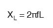
Since inductors drop voltage in proportion to the rate of current change, they will drop more voltage for faster-changing currents, and less voltage for slower-changing currents. What this means is that reactance in ohms for any inductor is directly proportional to the frequency of the alternating current. The exact formula for determining reactance is as follows:
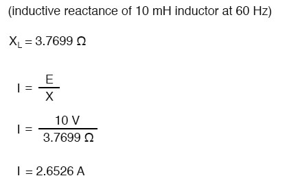
If we expose a 10 mH inductor to frequencies of 60, 120, and 2500 Hz, it will manifest the reactances in the table below.
Reactance of a 10 mH inductor:
| Frequency (Hertz) | Reactance (Ohms) |
| 60 | 3.7699 |
| 120 | 7.5398 |
| 2500 | 157.0796 |
In the reactance equation, the term “2πf” (everything on the right-hand side except the L) has a special meaning unto itself. It is the number of radians per second that the alternating current is “rotating” at, if you imagine one cycle of AC to represent a full circle’s rotation.
A radian is a unit of angular measurement: there are 2π radians in one full circle, just as there are 360° in a full circle. If the alternator producing the AC is a double-pole unit, it will produce one cycle for every full turn of shaft rotation, which is every 2π radians, or 360°.
If this constant of 2π is multiplied by frequency in Hertz (cycles per second), the result will be a figure in radians per second, known as the angular velocity of the AC system.
Angular Velocity in AC Systems
Angular velocity may be represented by the expression 2πf, or it may be represented by its own symbol, the lowercase Greek letter omega, which appears similar to our Roman lower-case “w”: ω. Thus, the reactance formula XL = 2πfL could also be written as XL = ωL.
It must be understood that this “angular velocity” is an expression of how rapidly the AC waveforms are cycling, a full-cycle being equal to 2π radians. It is not necessarily representative of the actual shaft speed of the alternator producing the AC.
If the alternator has more than two poles, the angular velocity will be a multiple of the shaft speed. For this reason, ω is sometimes expressed in units of electrical radians per second rather than (plain) radians per second, so as to distinguish it from mechanical motion.
Any way we express the angular velocity of the system, it is apparent that it is directly proportional to reactance in an inductor. As the frequency (or alternator shaft speed) is increased in an AC system, an inductor will offer greater opposition to the passage of current, and vice versa.
Alternating current in a simple inductive circuit is equal to the voltage (in volts) divided by the inductive reactance (in ohms), just as either alternating or direct current in a simple resistive circuit is equal to the voltage (in volts) divided by the resistance (in ohms). An example circuit is shown here:
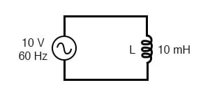
Inductive reactance
Phase Angles
However, we need to keep in mind that voltage and current are not in phase here. As was shown earlier, the voltage has a phase shift of +90° with respect to the current. If we represent these phase angles of voltage and current mathematically in the form of complex numbers, we find that an inductor’s opposition to current has a phase angle, too:
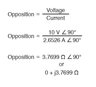
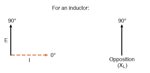
Current lags voltage by 90° in an inductor.
Mathematically, we say that the phase angle of an inductor’s opposition to current is 90°, meaning that an inductor’s opposition to current is a positive imaginary quantity. This phase angle of reactive opposition to current becomes critically important in circuit analysis, especially for complex AC circuits where reactance and resistance interact.
It will prove beneficial to represent any component’s opposition to current in terms of complex numbers rather than scalar quantities of resistance and reactance.
REVIEW:
- Inductive reactance is the opposition that an inductor offers to alternating current due to its phase-shifted storage and release of energy in its magnetic field. Reactance is symbolized by the capital letter “X” and is measured in ohms just like resistance (R).
- Inductive reactance can be calculated using this formula: XL = 2πfL
- The angular velocity of an AC circuit is another way of expressing its frequency, in units of electrical radians per second instead of cycles per second. It is symbolized by the lowercase Greek letter “omega,” or ω.
- Inductive reactance increases with increasing frequency. In other words, the higher the frequency, the more it opposes the AC flow of electrons.
RELATED WORKSHEETS:


Mistake in opposition calculations, current 2.6526A should have 0 deg shift not 90.