 Facebook
 Google
 GitHub
 Linkedin
Inductor Quirks
In an ideal case, an inductor acts as a purely reactive device. That is, its opposition to AC current is strictly based on inductive reaction to changes in current, and not electron friction as is the case with resistive components.
However, inductors are not quite so pure in their reactive behavior. To begin with, they’re made of wire, and we know that all wire possesses some measurable amount of resistance (unless it's superconducting wire).
This built-in resistance acts as though it were connected in series with the perfect inductance of the coil, like this:
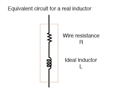
Inductor Equivalent circuit of a real inductor.
Consequently, the impedance of any real inductor will always be a complex combination of resistance and inductive reactance.
Compounding this problem is something called the skin effect, which is AC’s tendency to flow through the outer areas of a conductor’s cross-section rather than through the middle. When electrons flow in a single direction (DC), they use the entire cross-sectional area of the conductor to move.
Electrons switching directions of flow, on the other hand, tend to avoid travel through the very middle of a conductor, limiting the effective cross-sectional area available. The skin effect becomes more pronounced as frequency increases.
Also, the alternating magnetic field of an inductor energized with AC may radiate off into space as part of an electromagnetic wave, especially if the AC is of high frequency. This radiated energy does not return to the inductor, and so it manifests itself as resistance (power dissipation) in the circuit.
Eddy Currents in Inductors
Added to the resistive losses of wire and radiation, there are other effects at work in iron-core inductors which manifest themselves as additional resistance between the leads. When an inductor is energized with AC, the alternating magnetic fields produced tend to induce circulating currents within the iron core known as eddy currents.
These electric currents in the iron core have to overcome the electrical resistance offered by the iron, which is not as good a conductor as copper. Eddy current losses are primarily counteracted by dividing the iron core up into many thin sheets (laminations), each one separated from the other by a thin layer of electrically insulating varnish.
With the cross-section of the core divided up into many electrically isolated sections, current cannot circulate within that cross-sectional area and there will be no (or very little) resistive losses from that effect.
As you might have expected, eddy current losses in metallic inductor cores manifest themselves in the form of heat.
The effect is more pronounced at higher frequencies, and can be so extreme that it is sometimes exploited in manufacturing processes to heat metal objects!
In fact, this process of “inductive heating” is often used in high-purity metal foundry operations, where metallic elements and alloys must be heated in a vacuum environment to avoid contamination by air, and thus where standard combustion heating technology would be useless.
It is a “non-contact” technology, the heated substance not having to touch the coil(s) producing the magnetic field.
In high-frequency service, eddy currents can even develop within the cross-section of the wire itself, contributing to additional resistive effects. To counteract this tendency, special wire made of very fine, individually insulated strands called Litz wire (short for Litzendraht) can be used.
The insulation separating strands from each other prevent eddy currents from circulating through the whole wire’s cross-sectional area.
Additionally, any magnetic hysteresis that needs to be overcome with every reversal of the inductor’s magnetic field constitutes an expenditure of energy that manifests itself as resistance in the circuit.
Some core materials (such as ferrite) are particularly notorious for their hysteretic effect. Counteracting this effect is best done by means of proper core material selection and limits on the peak magnetic field intensity generated with each cycle.
Altogether, the stray resistive properties of a real inductor (wire resistance, radiation losses, eddy currents, and hysteresis losses) are expressed under the single term of “effective resistance:”
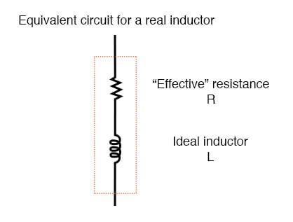
Equivalent circuit of a real inductor with skin-effect, radiation, eddy current, and hysteresis losses.
It is worthy to note that the skin effect and radiation losses apply just as well to straight lengths of wire in an AC circuit as they do a coiled wire. Usually, their combined effect is too small to notice, but at radio frequencies, they can be quite large.
A radio transmitter antenna, for example, is designed with the express purpose of dissipating the greatest amount of energy in the form of electromagnetic radiation.
Quality Factor (Q Factor)
Effective resistance in an inductor can be a serious consideration for the AC circuit designer. To help quantify the relative amount of effective resistance in an inductor, another value exists called the Q factor, or “quality factor” which is calculated as follows:

The symbol “Q” has nothing to do with an electric charge (coulombs), which tends to be confusing. For some reason, the Powers That Be decided to use the same letter of the alphabet to denote a totally different quantity.
The higher the value for “Q,” the “purer” the inductor is. Because it’s so easy to add additional resistance if needed, a high-Q inductor is better than a low-Q inductor for design purposes. An ideal inductor would have a Q of infinity, with zero effective resistance.
Because inductive reactance (X) varies with frequency, so will Q. However, since the resistive effects of inductors (wire skin effect, radiation losses, eddy current, and hysteresis) also vary with frequency, Q does not vary proportionally with reactance. In order for a Q value to have a precise meaning, it must be specified at a particular test frequency.
RELATED WORKSHEETS:


