Facebook
 Google
 GitHub
 Linkedin
Frequency Compensation of Amplifier Circuits
Negative feedback is a wonderful thing. We take the inverted output signal, subtract it from the input signal, and the amplifier will automatically correct the difference between them. If we only feed back a fraction of the output signal, the amplifier will automatically adjust its gain to one over that fraction.
When Negative Feedback Causes Oscillation
For a single frequency, inverting the signal (negative feedback) is the same as a 180-degree phase shift. And here comes the problem: each device in the amplifier has a little bit of delay. At low frequencies, this has little effect. As we go higher and higher in frequency, the delay becomes more and more noticeable.
At some high frequency, the delay amounts to half a period of the signal and thus causes a phase shift of 180 degrees. The 180-degree delay plus the 180-degree inversions results in a 360-degree total phase shift. What started out as negative feedback now becomes positive feedback, and the whole thing oscillates.
Frequency Compensation to the Rescue
Frequency compensation is a design method that avoids oscillation. The principle is very simple: deliberately slow down one device so that it is much slower than all others. This device then dominates the frequency response, rendering the delay in all other devices unimportant.
We can illustrate this with a very simple simulation. Figure 8-1 shows the example circuit we’ll use.
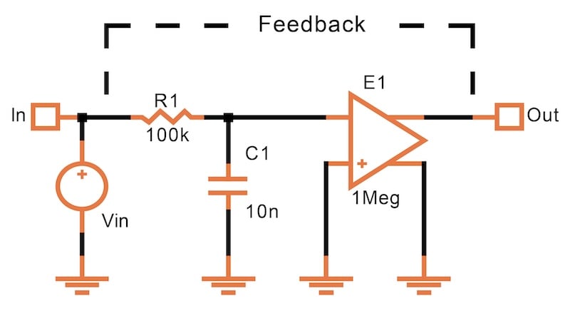
Figure 8-1. Example circuit to illustrate phase shift in a feedback amplifier.
In the above circuit, E1 is a voltage-controlled voltage source with the following characteristics:
- It acts like an ideal op amp with a gain of 1 million (120 dB).
- It has no delay.
- Its input and output terminals are free-floating (though they’re referenced here to ground).
R1 and C1 cause the single delay—in other words, the phase shift. Figure 8-2 shows the simulation results for the circuit of Figure 8-1.
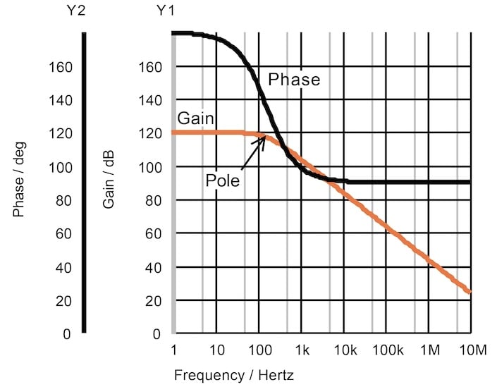
Figure 8-2. In a single-pole circuit, the phase never goes below 90 degrees.
Due to the RC network, the amplitude at the output (gain) starts decreasing at about 100 Hz. At this point, the phase of the signal at the output is considerably less than 180 degrees. As we go higher in frequency, though, the phase never goes below 90 degrees. The signal being fed back to the input can’t reach a phase shift of zero degrees, which is the condition for oscillation.
The point at which the phase has decreased by 45 degrees is called a pole. At frequencies somewhat higher than the pole, the amplitude drops by 6 dB per octave (doubling of frequency) or 20 dB per decade.
Frequency Response of a Two-Pole System
Figure 8-3 shows the same simulation with a second RC network added at the output—one with a pole at a much higher frequency (C2 = 100 pF ≪ C1 = 10 nF).
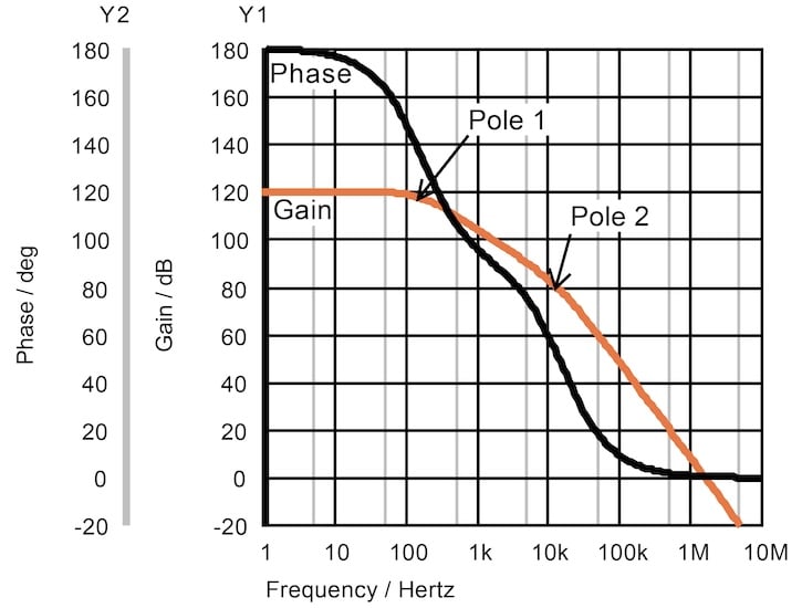
Figure 8-3. With two poles in a feedback path, the phase approaches zero degrees.
We now have two poles—you can just barely see the second pole (at about 10 kHz) by the change in the steepness of the gain curve. The maximum phase shift now is 180 degrees.
The point of interest is the frequency at which the gain moves through 0 dB (i.e. a gain of one). In Figur 8-3, this unity gain frequency is just above 1 MHz. If the gain is less than one at this frequency, an oscillation can’t sustain itself. While the phase at this point only approaches zero degrees, the margin is far too close for comfort.
Frequency Response of a Three-Pole System
Finally, Figure 8-4 shows the gain and phase plot for a three-pole circuit. With three poles, we’re clearly out of luck. The phase now reaches zero degrees a decade before the gain drops below 0 dB.
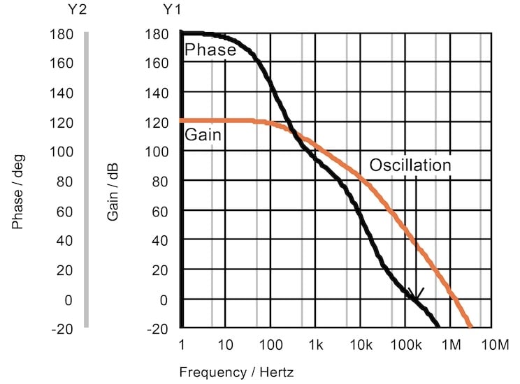
Figure 8-4. Three poles in a feedback path cause the phase shift to pass through zero degrees, and oscillation takes place.
An amplifier that has these three poles will oscillate. In fact, we can tell with certainty that it will oscillate at 200 kHz.
There are three remedies for this problem:
- We can lower the gain until it drops below 0 dB before the phase reaches zero degrees.
- We can insert a new pole at a frequency so low that it dominates the others.
- We can introduce a zero.
Introducing Zeros
To illustrate the effect of a zero, we use another artificial circuit (Figure 8-5).
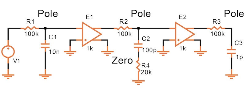
Figure 8-5. Circuit with three poles and a zero.
R1-C1, R2-C2, and R3-C3 provide the three poles. Each delays the phase of the signal by the same amount as in Figure 8-4. In Figure 8-6, the combination of R4-C2 provides the zero, which starts turning back the phase at about 30 kHz.
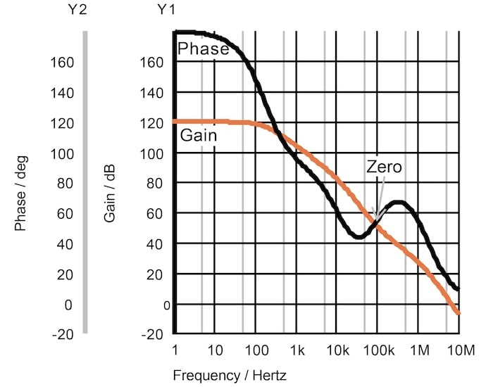
Figure 8-6. A zero increases the phase (reduces the phase shift).
The value of R4 is selected to result in a frequency where the zero is most effective. At the critical unity-gain frequency (5 MHz), the gain drops below 0 dB, but the phase is still positive (about 15 degrees). The phase at which the gain drops below 0 dB is called the phase margin.
Theoretically, a feedback circuit with this behavior will not oscillate, though the phase margin is rather low. Since gain and time constants are subject to variation in an IC, it should be at least 60 degrees in your designs.