Facebook
 Google
 GitHub
 Linkedin
The Phase Detector
To get a feel for the operation of a phase-locked loop, you need to understand its key component: the phase detector. The circuit in Figure 14-2, known as the four-quadrant multiplier, is one of several schemes used as phase detectors.
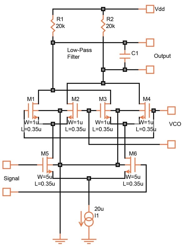
Figure 14-2. The phase detector. [click to enlarge]
This circuit includes a straightforward differential pair (M5 and M6) that amplifies a signal arriving from outside the IC. However, instead of the drains being connected to load resistors or an active load, their currents pass through four other transistors. These transistors (M1, M2, M3, and M4) are turned ON and OFF by a local voltage-controlled oscillator (VCO).
The DC bias levels of the signal inputs must be high enough to exceed the threshold voltages. Typically, this is 1.0 or 1.5 V.
The VCO Waveform
Imagine a square wave at the VCO input with a frequency exactly the same as that of the input signal. This could be a rail-to-rail, two-phase, square wave. Preferably, though, it should be a waveform centered at about 2 V DC and moving ± 200 mV differentially. This is illustrated in Figure 14-3.
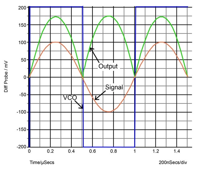
Figure 14-3. With the VCO signal in phase, the output is a rectified sine wave with a positive average.
At first, as we see above, the VCO waveform is in phase with the input signal. Here, 'in phase' means that the two cross zero at the same time.
During the first phase of the VCO signal, the drain of M5 is connected through M1 to R1. The drain of M6 is connected through M4 to R2. During the second phase, this connection reverses: The drain current of M5 flows through M2 and R2, while that of M6 flows through M3 and R1. Thus, ignoring C1 for now, the output across the two load resistors is a rectified sine wave with a positive average value.
Next, let's keep the frequencies the same but shift the phase of the VCO signal by 90 degrees (Figure 14-4).
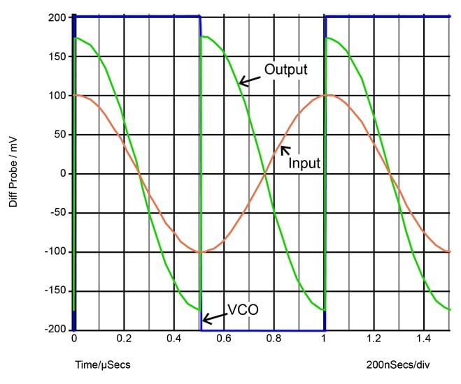
Figure 14-4. With the phase of the VCO signal shifted by 90 degrees, the average of the output voltage is zero.
The signal is now chopped at the moment it reaches its peak amplitude, and the output shows equal positive and negative excursions. The average differential output voltage is therefore zero.
Finally, Figure 14-5 shows what happens if we shift the VCO waveform a further 90 degrees. We’ll still keep its frequency constant.
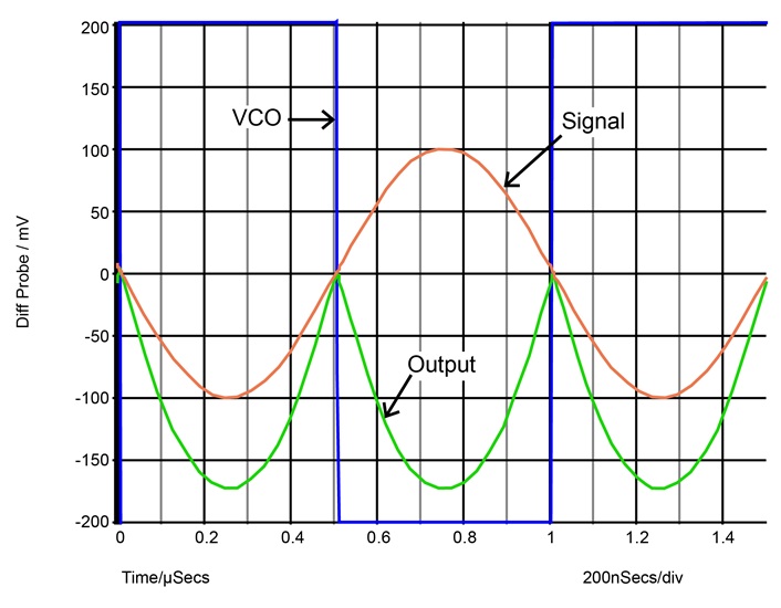
Figure 14-5. With a 180 degree phase shift, the average of the output is negative.
Once again, the VCO waveform chops the signal at the zero crossings. However, the output is now inverted. Averaging it with C1 results in a negative voltage. We thus have a DC (or low-frequency) signal at the output of the phase detector. This "error" signal is a measure of the relative phases of the two frequencies.