Facebook
 Google
 GitHub
 Linkedin
Operation of a PLL
If we use the error signal to adjust the frequency of the voltage-controlled oscillator (VCO), we have the phase-locked loop (Figure 14-6).
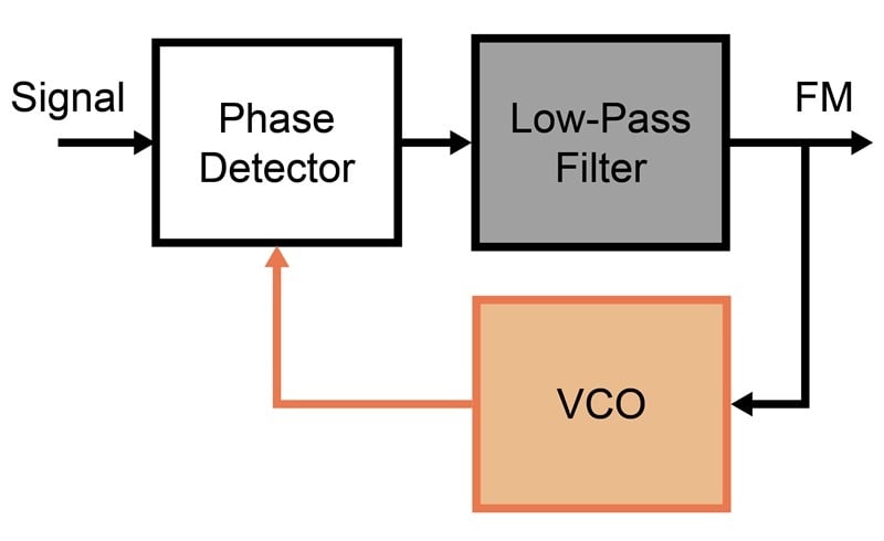
Figure 14-6. Block diagram of a simple phase-locked loop.
Let's say the VCO is running at 1 MHz and the input signal is 800 kHz. Here, in slow motion, is what will happen.
Since the two frequencies are not synchronized, there’s no phase relationship yet. At this point, the phase detector is merely a mixer. As a mixer, the phase detector produces several new frequencies, including the difference between the two frequencies and various combinations of harmonics. The one of interest is the difference, 200 kHz. It’s still too high to pass through the filter.
As we move the input signal gradually higher in frequency, there comes a point where the difference frequency is low enough that some of the signal passes through the filter and starts influencing the VCO. The signal is not rectified yet—it’s still AC—but the VCO starts to jitter around its free-running frequency. If we move the input signal just a little higher in frequency, the jitter suddenly disappears, and the VCO jumps into step with the input signal. We now see a DC level at the output of the filter.
As you continue to move the input signal higher in frequency, the VCO will continue to track it until the loop finally runs out of control voltage. This is illustrated in Figure 14-7, where the signal frequency is swept from low to high over a 5 ms period.
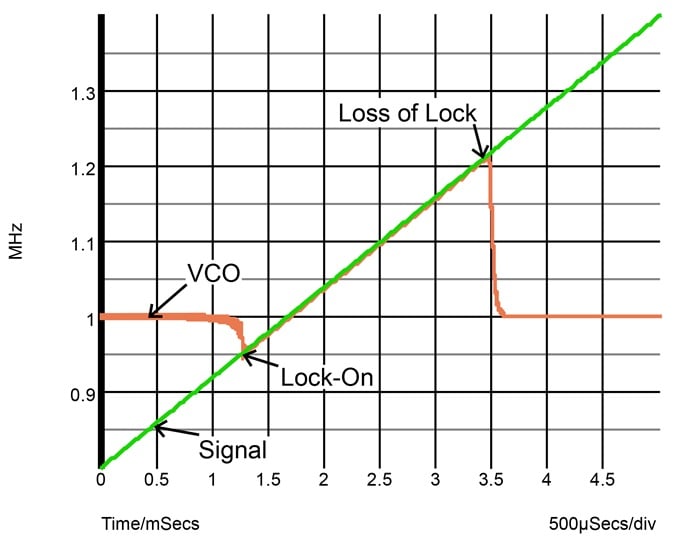
Figure 14-7. Locking behavior of a phase-locked loop.
The exact same behavior is seen as you approach the VCO frequency from the high end. The capture range, which is the maximum difference between the two frequencies to achieve lock-on, is always narrower than the lock range, which is how far you can drag the VCO and still keep lock. It makes no difference which frequency is moved and which is fixed.
Both the capture range and the lock range are influenced by loop gain and signal level. If you increase the gain of the loop or the input signal level, both ranges become wider.
Strictly speaking, the name phase-locked loop is a misnomer. As you move through the lock range, the two frequencies are locked, but their phase relationship has to change to produce the error signal. This means that the phase is not locked. Frequency-locked loop would be a better name.
Important Characteristics of the PLL
The phase-locked loop has three important characteristics, especially for integrated circuits:
- The capture range is determined by a lowpass filter as well as the loop gain.
- The VCO doesn’t need to be very accurate.
- Frequency deviation can be measured using the error signal.
Filtering
Apart from the loop gain, the capture range is determined by a single lowpass filter. For example, if the signal you are looking for is at 50 MHz and has a narrow bandwidth (say, 5 kHz), you dimension the lowpass filter so it rolls off at about 5 kHz. This makes the phase-locked loop look like a very sharp bandpass filter.
A single-pole lowpass filter rolls off at 20 dB per decade. At 49.9 MHz and 50.1 MHz, the interfering signal is therefore attenuated at the lowpass filter by 26 dB. Using an active filter, it would take many poles and a large number of precision components to achieve the same selectivity.
The phase-locked loop depicted in Figure 14-6 is a second-order PLL, meaning that it has two poles: one from the VCO itself, the other from the lowpass filter. This configuration is unconditionally stable.
Adding another pole makes stability (the absence of unwanted oscillation) more difficult to achieve. However, it doubles the sharpness of the filter action.
VCO Tolerance
The VCO need not be highly accurate. As long as the free-running frequency is within the capture range of the signal, the loop will find the exact frequency. If your capture range is very narrow, however, the loop may have difficulty acquiring the signal.
In the example above, the free-running frequency would have to be within 5 kHz (0.1%) of the signal. Without using accurate components, such precision can only be achieved by tuning. For example, we would need to start by sweeping the VCO over a wider range. Once we have detected the frequency capture, we would stop the sweep.
Frequency Deviation
The error signal is a measure of frequency deviation. As you may recall, the error signal is the output of the lowpass filter. If the input signal is frequency-modulated (FM), this output is the demodulated signal.
Designing a PLL for AM Modulation
As illustrated in Figure 14-8, there's even a simple PLL design if the modulation is AM rather than FM.
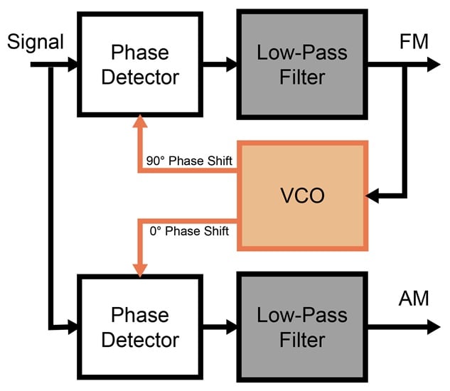
Figure 14-8. Phase-locked loop with AM output.
The VCO now has two outputs. Both have the same frequency, but the second output is shifted by 90 degrees. A second phase detector and lowpass filter are also added.
In the middle of the lock range, the phase shift between the signal and the VCO is automatically 90 degrees. The control voltage for the VCO is therefore zero. This means that the signal frequency is chopped at the amplitude peaks.
A second phase detector operating at 0 degrees phase shift will chop the same signal at the zero crossing. The result is a voltage proportional to amplitude. The AM output in Figure 14-8 is the demodulated AM signal and also indicates that the loop is locked.