This page explains what quadrature demodulation is and provides insight into the nature of I/Q signals.
If you have read the previous page, you know what I/Q signals are and how quadrature (i.e., I/Q-signal-based) modulation is accomplished. In this page we’ll discuss quadrature demodulation, which is a versatile technique for extracting information from amplitude-, frequency-, and phase-modulated waveforms.
The following diagram conveys the basic structure of a quadrature demodulator.
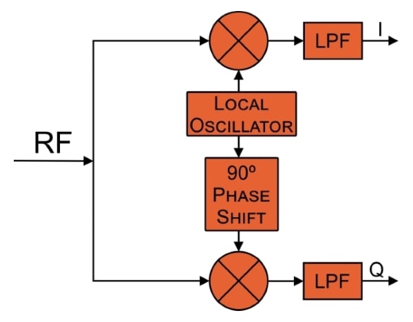
You will readily notice that the system is similar to a quadrature modulator in reverse. The RF signal is multiplied by the local oscillator signal (for the I channel) and the local oscillator shifted by 90° (for the Q channel). The result (after low-pass-filtering, which will be explained shortly) are I and Q waveforms that are ready for further processing.
In quadrature modulation, we use baseband I/Q signals to create an amplitude-, frequency-, or phase-modulated waveform that will be amplified and transmitted. In quadrature demodulation, we are converting the existing modulation into the corresponding I/Q baseband signals. It’s important to understand that the received signal could be from any sort of transmitter—quadrature demodulation is not limited to signals that were originally created through quadrature modulation.
The low-pass filters are needed because the quadrature multiplication applied to the received signal is no different from the multiplication employed in, for example, an ordinary AM demodulator. The received spectrum will be shifted downward and upward by the carrier frequency (fC); thus, a low-pass filter is needed to suppress the high-frequency content associated with the spectrum centered around 2fC.
If you’ve read the page on amplitude demodulation, the preceding paragraph may have caused you to realize that a quadrature demodulator is actually composed of two amplitude demodulators. Of course, you cannot apply ordinary amplitude demodulation to a frequency-modulated signal; there is no information encoded in the FM signal’s amplitude. But quadrature (amplitude) demodulation can capture the frequency-encoded information—this is simply the (rather interesting) nature of I/Q signals. By using two amplitude demodulators driven by carrier-frequency sinusoids with a 90° phase difference, we generate two different baseband signals that together can convey information encoded via changes in the received signal’s frequency or phase.
As mentioned in the first page of this chapter, How to Demodulate an AM Waveform, one approach to amplitude demodulation involves multiplying the received signal by a carrier-frequency reference signal, and then low-pass-filtering the result of this multiplication. This method provides higher performance than AM demodulation that is built around a leaky peak detector. However, this approach has a serious weakness: the result of the multiplication is affected by the phase relationship between the transmitter’s carrier and the receiver’s carrier-frequency reference signal.
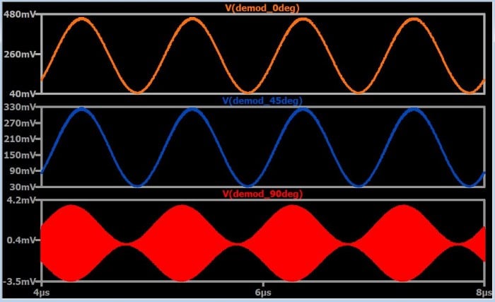
These plots show the demodulated signal for three values of transmitter-to-receiver phase difference. As the phase difference increases, the amplitude of the demodulated signal decreases. The demodulation procedure has become nonfunctional at 90° phase difference; this represents the worst-case scenario—i.e., the amplitude begins to increase again as the phase difference moves away (in either direction) from 90°.
One way to remedy this situation is through additional circuitry that synchronizes the phase of the receiver’s reference signal with the phase of the received signal. However, quadrature demodulation can be used to overcome the absence of synchronization between transmitter and receiver. As was just pointed out, the worst-case phase discrepancy is ±90°. Thus, if we perform multiplication with two reference signals separated by 90° of phase, the output from one multiplier compensates for the decreasing amplitude of the output from the other multiplier. In this scenario the worst-case phase difference is 45°, and you can see in the above plot that a 45° phase difference does not result in a catastrophic reduction in the amplitude of the demodulated signal.
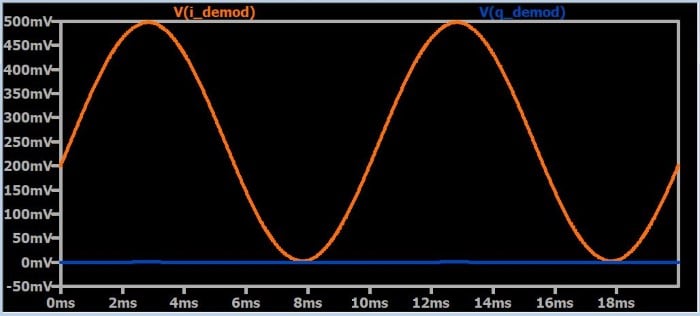
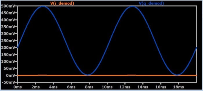
The following plots demonstrate this I/Q compensation. The traces are demodulated signals from the I and Q branches of a quadrature demodulator.
Transmitter phase = 0°
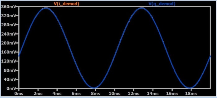
Transmitter phase = 45°
(the orange trace is behind the blue trace—i.e., the two signals are identical)
Transmitter phase = 90°
It would be convenient if we could combine the I and Q versions of the demodulated signal into one waveform that maintains a constant amplitude regardless of the phase relationship between transmitter and receiver. Your first instinct might be to use addition, but unfortunately it’s not that simple. The following plot was generated by repeating a simulation in which everything is the same except the phase of the transmitter’s carrier. The phase value is assigned to a parameter that has seven distinct values: 0°, 30°, 60°, 90°, 120°, 150°, and 180°. The trace is the sum of the demodulated I waveform and the demodulated Q waveform.
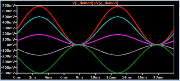
As you can see, addition is certainly not the way to produce a signal that is not affected by variations in the transmitter-to-receiver phase relationship. This is not surprising if we remember the mathematical equivalence between I/Q signaling and complex numbers: the I and Q components of a signal are analogous to the real and imaginary parts of a complex number. By performing quadrature demodulation, we obtain real and imaginary components that correspond to the magnitude and phase of the baseband signal. In other words, I/Q demodulation is essentially translation: we are translating from a magnitude-plus-phase system (used by a typical baseband waveform) to a Cartesian system in which the I component is plotted on the x-axis and the Q component is plotted on the y-axis.
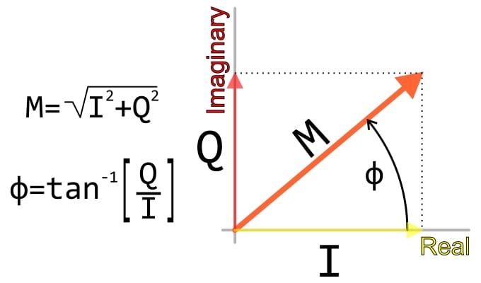
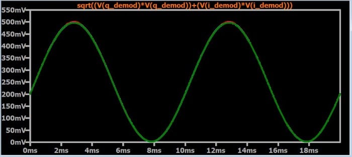
To obtain the magnitude of a complex number, we can’t simply add the real and imaginary parts, and the same applies to I and Q signal components. Instead, we have to use the formula shown in the diagram, which is nothing more than the standard Pythagorean approach to finding the length of the hypotenuse of a right triangle. If we apply this formula to the I and Q demodulated waveforms, we can obtain a final demodulated signal that is not affected by phase variations. The following plot confirms this: the simulation is the same as the previous one (i.e., seven different phase values), but you see only one signal, because all the traces are identical.

In Partnership with AMETEK Programmable Power

by Aaron Carman


