Facebook
 Google
 GitHub
 Linkedin
Integrated Circuits
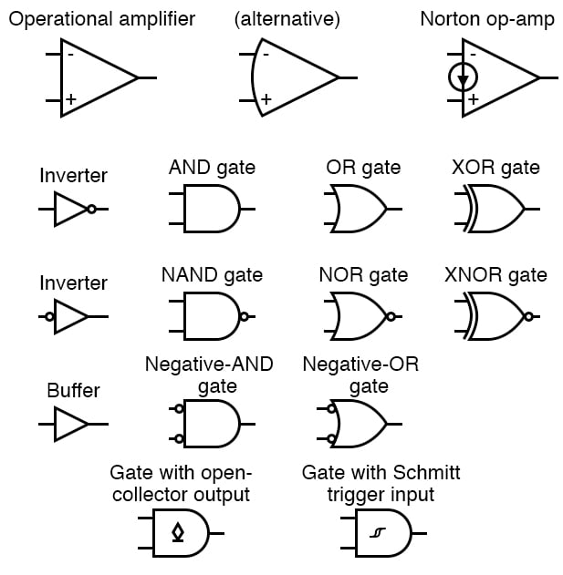
A Logic Gate is assigned as an elementary building block of digital circuits.
Logic gate is considered as a device which has the ability to produce one output level with the combinations of input levels.
Inputs and outputs of logic gates are in two levels termed as HIGH and LOW, or TRUE and FALSE, or ON and OFF, or simply 1 and 0.
The AND gate produces an output of logic 1 state when each of the inputs are at logic 1 state and also produces an output of logic 0 state even if any of its inputs are at logic 0 state.
Similar to AND gate, an OR gate may also have two or more inputs but produce only one output.
The OR gate produces an output of logic 1 state even if any of its inputs is in logic 1 state and also produces an output of logic 0 state if any of its inputs is in logic 0 state.
The NOT gate is also called as an inverter, simply because it changes the input to its opposite.
The NOT gate is having only one input and one corresponding output. It is a device whose output is always the complement of the given input.
That means, the NOT gate produces an output of logic 1 state when the input is of logic 0 state and also produce the output of logic 0 state when the input is of logic 1 state.
The NAND and NOR gates are the universal gates. Each of this gates can realize the logic circuits single handedly.
The NAND and NOR are also called as universal building blocks. Both NAND and NOR has the ability to perform three basic logic functions such as AND,OR and NOT.
NAND gate is a combination of an AND gate and a NOT gate. NOR gate is a combination of an OR gate and a NOT gate.
RELATED WORKSHEETS:
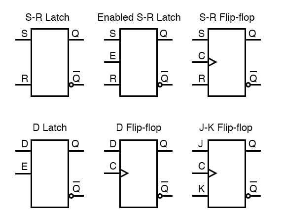
- Flip-Flop Circuits Worksheet
- Latch Circuits Worksheet
- Basic Logic Gates Worksheet
- Basic Operational Amplifiers Worksheet