Facebook
 Google
 GitHub
 Linkedin
Basic Electricity
Basic Electromagnetic Relays
11 questions By Tony R. Kuphaldt
-
Question 7 of 11
Complete the schematic diagram for a SPDT relay circuit that energizes the green light bulb (only) when the pushbutton switch is pressed, and energizes the red light bulb (only) when the pushbutton switch is released:

Reveal answerIn order for this circuit to function as specified, the green light bulb must receive power through the relay’s normally-open contact, and the red light bulb through the relay’s normally-closed contact.
Notes:If any students ask what “SPDT” means, refer them to a text or other information source on switch contacts in general (SPST, SPDT, DPST, DPDT, etc.).
Ground symbols were used intentionally in this question, to eliminate clutter from the diagram, and also to make students more familiar with their use as a notation for a common (reference) point in a circuit.
This question also reveals another useful feature of relays, and that is logic inversion. The green light operates in the same mode as the pushbutton switch, but the red light is opposite of the pushbutton switch. With just a single pushbutton operator, two complementary functions may be performed through the use of a SPDT relay.
-
Question 8 of 11
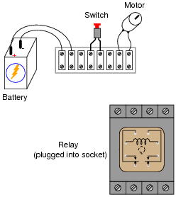
Small relays often come packaged in clear, rectangular, plastic cases, which had led to the name ice cube relay to be commonly applied to them. These so-called “ice cube” relays have either eight or eleven pins protruding from the bottom, allowing them to be plugged into a special socket for connection with wires in a circuit:

Draw the necessary connecting wires between terminals in this circuit, so that actuating the normally-open pushbutton switch will energize the relay, which will in turn supply electrical power to the motor.
Reveal answerThis is by no means the only solution, but it works:
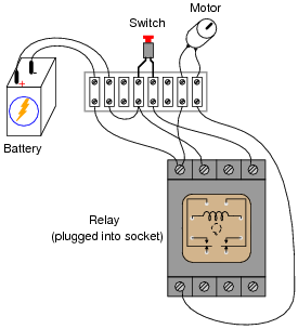
Notes:“Ice cube” style relays are very common in industry, and it is important that students understand how to interpret the pin diagrams on the cases in order to use them in new circuits and to troubleshoot relay circuits that are already built.
-
Question 9 of 11
Suppose that an electromechanical relay has a coil voltage rating of 5 volts, and a coil resistance of 250 Ω. However, you desire to energize this relay with a 24 volt power supply. You know that a series-connected resistor might enable the 5-volt relay coil to be powered by the 24-volt supply without damage, but you do not know what size of resistor would be appropriate for the task.
Draw a schematic diagram for such a circuit, showing the power supply (battery symbol), relay, and resistor. Explain how the resistor’s value would be calculated, along with the calculated value in ohms.
Reveal answerResistor value = 950 Ω.
Notes:Do not be surprised if many of your students neglect to calculate the resistor’s necessary power dissipation rating for the resistor, simply because this value was not requested in the question. However, it is important for students to be actively thinking about every problem they encounter, and to try to take all relevant factors into consideration!
In real life, the power dissipation rating of such a resistor would be very important. Failing to account for this value could result in component (and system) failure.