 Facebook
 Google
 GitHub
 Linkedin
AC Electric Circuits
Basic Oscilloscope Operation
25 questions By Tony R. Kuphaldt
-
Question 1 of 25
An oscilloscope is a very useful piece of electronic test equipment. Most everyone has seen an oscilloscope in use, in the form of a heart-rate monitor (electrocardiogram, or EKG) of the type seen in doctor’s offices and hospitals.
When monitoring heart beats, what do the two axes (horizontal and vertical) of the oscilloscope screen represent?
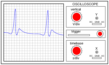
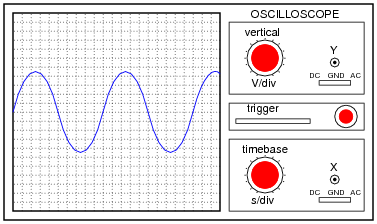
In general electronics use, when measuring AC voltage signals, what do the two axes (horizontal and vertical) of the oscilloscope screen represent?
Reveal answerEKG vertical = heart muscle contraction ; EKG horizontal = time
General-purpose vertical = voltage ; General-purpose horizontal = time
Notes:Oscilloscope function is often best learned through interaction. Be sure to have at least one oscilloscope operational in the classroom for student interaction during discussion time.
-
Question 2 of 25
The core of an analog oscilloscope is a special type of vacuum tube known as a Cathode Ray Tube, or CRT. While similar in function to the CRT used in televisions, oscilloscope display tubes are specially built for the purpose of serving an a measuring instrument.
Explain how a CRT functions. What goes on inside the tube to produce waveform displays on the screen?
Reveal answerThere are many tutorials and excellent reference books on CRT function - go read a few of them!
Notes:Some of your students may come across photographs and illustrations of CRTs for use in their presentation. If at all possible, provide a way for individual students to share their visual findings with their classmates, through the use of an overhead projector, computer monitor, or computer projector. Discuss in detail the operation of a CRT with your students, especially noting the electrostatic method of electron beam deflection used to “steer” the beam to specific areas on the screen.
-
Question 3 of 25
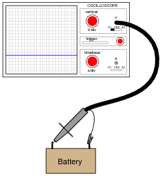
When the vertical (“Y”) axis of an oscilloscope is shorted, the result should be a straight line in the middle of the screen:
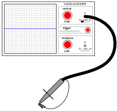
Determine the DC polarity of the voltage source, based on this illustration:
Reveal answer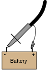
Notes:This question challenges students to figure out both the polarization of the probe (and ground clip), as well as the orientation of the Y axis. It is very important, of course, that the coupling control be set on “DC” in order to successfully measure a DC signal.


this is so helpful thank you
Veľká vďaka za poučný článok. Ešte keby tam bolo napísané, ako sa vypočítala tá frekvencia 400 Hz, 40 Hz, 6,67 kHz