Facebook
 Google
 GitHub
 Linkedin
AC Electric Circuits
Characteristic Impedance
17 questions By Tony R. Kuphaldt
-
Question 13 of 17
A two-conductor cable of uniform construction will exhibit a uniform characteristic impedance (Z0) due to its intrinsic, distributed inductance and capacitance:
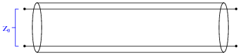
What would happen to the value of this characteristic impedance if we were to shorten the cable’s length, all other dimensions remaining the same?
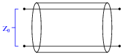
Reveal answerZ0 would remain exactly the same!
Follow-up question: what electrical characteristics would change for this shortened cable?
Notes:This is sort of a “trick” question, designed to make students think about characteristic impedance, and to test their real comprehension of it. If a student properly understands the physics resulting in characteristic impedance, they will realize length has nothing whatsoever to do with it. Although the cable’s total capacitance will change as a result of shortening the cable’s length, and the cable’s total inductance will likewise decrease for the same reason, these electrical changes should not present a conceptual difficulty to students unless they are modeling the cable in terms of one lumped capacitance and one (or two) lumped inductance(s). If they are thinking in these terms, they have not yet fully grasped the reason why characteristic impedance exists at all.
-
Question 14 of 17
Suppose we were designing a pair of BJT amplifier circuits to connect to either end of a long two-conductor cable:
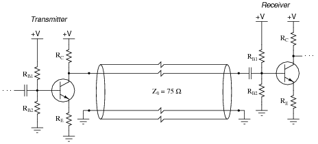
How would we choose the component values in each transistor amplifier circuit to naturally terminate both ends of the 75 Ω cable?
Reveal answerRC of the transmitting amplifier should be 75 Ω, as should the parallel equivalent resistance RB1 || RB2 of the receiving amplifier.
Notes:This question is really a review of Thévenin’s theorem as it applies to common-emitter, divider-biased BJT amplifier circuits.
In case anyone asks, the “zig-zags” in the four lines for the cable represent an unspecified distance between those points. In other words, the cable is longer than what may be proportionately represented on the schematic diagram.
-
Question 15 of 17
Suppose we were designing a pair of BJT amplifier circuits to connect to either end of a long two-conductor cable, each end coupled to its respective amplifier through a transformer:
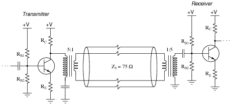
How would we choose the component values in each transistor amplifier circuit to naturally terminate both ends of the 75 Ω cable?
Reveal answerRC of the transmitting amplifier should be 1.875 kΩ, as should the parallel equivalent resistance RB1 || RB2 of the receiving amplifier.
Notes:This question is really a review of Thévenin’s theorem as it applies to common-emitter, divider-biased BJT amplifier circuits, and also impedance transformation as it applies to step-up and step-down transformers.
In case anyone asks, the “zig-zags” in the four lines for the cable represent an unspecified distance between those points. In other words, the cable is longer than what may be proportionately represented on the schematic diagram.