Facebook
 Google
 GitHub
 Linkedin
Network Analysis Techniques
Component Modeling
5 questions By Tony R. Kuphaldt
-
Question 4 of 5
A transistor is a semiconductor device that acts as a constant-current regulator. For the sake of analysis, transistors are often considered as constant-current sources:
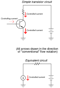
Suppose we needed to calculate the amount of current drawn from the 6-volt source in this dual-source transistor circuit:

We know the combined currents from the two voltage sources must add up to 5 mA, because Kirchhoff’s Current Law tells us that currents add algebraically at any node. Based on this knowledge, we may label the current through the 6-volt battery as “I”, and the current through the 7.2 volt battery as “5 mA − I”:
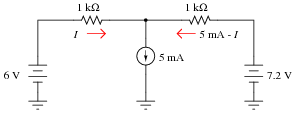
Kirchhoff’s Voltage Law tells us that the algebraic sum of voltage drops around any “loop” in a circuit must equal zero. Based on all this data, calculate the value of I:
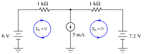
Hint: simultaneous equations are not needed to solve this problem!
Reveal answerI = 1.9 mA
Notes:I wrote this question in such a way that it mimics branch/mesh current analysis, but with enough added information (namely, the current source’s value) that there is only one variable to solve for. The idea here is to prepare students for realizing why simultaneous equations are necessary in more complex circuits (when the unknowns cannot all be expressed in terms of a single variable).
-
Question 5 of 5
Models of complex electronic components are useful for circuit analysis, because they allow us to express the approximate behavior of the device in terms of ideal components with relatively simple mathematical behaviors. Transistors are a good example of components frequently modeled for the sake of amplifier circuit analysis:
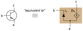
It must be understood that models are never perfect replicas of the real thing. At some point, all models fail to precisely emulate the thing being modeled. The only real concern is how accurate we want our approximation to be: which characteristics of the component most concern us, and which do not.
For example, when analyzing the response of transistor amplifier circuits to small AC signals, it is often assumed that the transistor will be “biased” by a DC signal such that the base-emitter diode is always conducting. If this is the case, and all we are concerned with is how the transistor responds to AC signals, we may safely eliminate the diode junction from our transistor model:
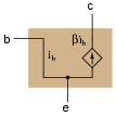
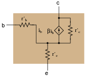
However, even with the 0.7 volt (nominal) DC voltage drop absent from the model, there is still some impedance that an AC signal will encounter as it flows through the transistor. In fact, several distinct impedances exist within the transistor itself, customarily symbolized by resistors and lower-case r′ designators:
From the perspective of an AC current passing through the base-emitter junction of the transistor, explain why the following transistor models are equivalent:
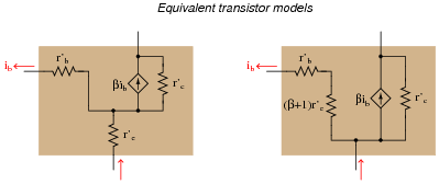
Reveal answerThese two models are equivalent because a given current (ib) will cause the exact same amount of voltage drop between base and emitter \((v=ir)\):
$$v = i_b r’_b + (i_b+\beta i_b) r’_e \ \ \ \ \ \ \ \ \ \ \ \ Left-hand\ model$$
$$v = i_b [{r'_b + (\beta + 1) r'_e})] \ \ \ \ \ \ \ \ \ \ \ \ Right-hand\ model$$
The mathematical equivalence of these two expressions may be shown by factoring ib from all the terms in the left-hand model equation.
Notes:The purpose of this question is to introduce students to the concept of BJT modeling, and also to familiarize them with some of the symbols and expressions commonly used in these models (as well as a bit of DC resistor network theory and algebra review, of course!).