
 Facebook
 Google
 GitHub
 Linkedin
AC Electric Circuits
Delta and Wye 3-Phase Circuits
15 questions By Tony R. Kuphaldt
-
Question 13 of 15
Identify the primary-secondary connection configuration of these pole-mounted power transformers (i.e. Y-Y, Y-Delta, Delta-Y, etc.):
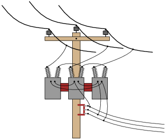
Reveal answerThese transformers are connected in a Y-Delta configuration.
Notes:Being that pole-mounted power distribution transformers are exposed for anyone to look at, they provide an excellent opportunity for students to practice identifying three-phase connections. If there are any such transformer configurations located near your campus, it would be an interesting field exercise to bring students there (or send them there on “field research”!) to identify the connections. Photographs of transformer connections may also be used in the classroom to provide practical examples of this concept.
-
Question 14 of 15
Identify the primary-secondary connection configuration of these pole-mounted power transformers (i.e. Y-Y, Y-Delta, Delta-Y, etc.):
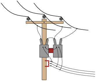
Reveal answerThese transformers are connected in an open-Delta configuration.
Notes:Understanding the open-Delta configuration is made easier if students first understand the robustness of the regular Delta configuration: how it continues to provide true three-phase power with no degradation in line voltage in the event of a winding failure. Discuss the advantages and disadvantages of such a configuration with your students.
-
Question 15 of 15
One of the conductors connecting the secondary of a three-phase power distribution transformer to a large office building fails open. Upon inspection, the source of the failure is obvious: the wire overheated at a point of contact with a terminal block, until it physically separated from the terminal.

What is strange, though, is that the overheated wire is the neutral conductor, not any one of the “line” conductors. Based on this observation, what do you think caused the failure?
After repairing the wire, what would you do to verify the cause of the failure?
Reveal answerHere’s a hint: if you were to repair the neutral wire and take current measurements with a digital instrument (using a clamp-on current probe, for safety), you would find that the predominant frequency of the current is 180 Hz, rather than 60 Hz.
Notes:This scenario is all too common in modern power systems, as non-linear loads such as switching power supplies and electronic power controls become more prevalent. Special instruments exist to measure harmonics in power systems, but a simple DMM (digital multimeter) may be used as well to make crude assessments such as the one described in the Answer.
Related Tools:
- Electrical Conduction in Semiconductors
- Performance-Based Assessments for Digital Circuit Competencies



Great information I’m sure, but the answers with diagrams can’t be read. They are blurry if you try to enlarge them and they aren’t on the PDF. Please resolve at your convenience.