Facebook
 Google
 GitHub
 Linkedin
Discrete Semiconductor Devices and Circuits
Differential Transistor Amplifiers
19 questions By Tony R. Kuphaldt
-
Question 7 of 19
Would you characterize this transistor amplifier as being inverting or noninverting, with the base terminal of transistor Q1 being considered the input? Explain your answer.

Reveal answerThis is a noninverting amplifier.
Follow-up question: what happens to the collector-emitter conductivity of transistor Q2 as transistor Q1 passes more current due to an increasing Vin signal?
Notes:Analysis of this circuit is aided by applying the “variable resistor” model of the transistor to it. Substitute variable resistors for the transistors Q1 and Q2, and then have your students analyze it as a voltage divider circuit.
The follow-up question is important because it implies transistor Q2 is not a static entity with changes in Q1’s base signal. The same may be said for Q1 when changes occur at the base of Q2. Discuss this effect with your students, making sure they understand why both transistors’ conductivity changes with a change in only one of the base voltages.
-
Question 8 of 19
Here, a differential pair circuit is driven by an input voltage at the base of Q2, while the output is taken at the collector of Q2. Meanwhile, the other input (Q1 base) is connected to ground:

Identify what types of amplifier circuits the two transistors are functioning as (common-collector, common-emitter, common-base) when the differential pair is used like this, and write an equation describing the circuit’s voltage gain. Here is another schematic, showing the transistors modeled as controlled current sources, to help you with the equation:
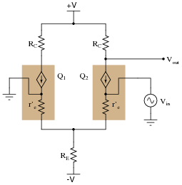
Reveal answerQ2 operates as a common-emitter amplifier, while Q1 does not really act as an amplifier at all (given that no input or output connects to it). The gain equation is as such:
$$A_{V(invert)}= \frac{R_C}{r'_e+(r'_e||R_E)}$$
Follow-up question #1: explain why it is appropriate to simplify the gain equation to this:
$$A_{V(invert)}\approx \frac{R_C}{2r'_e}$$
Follow-up question #2: explain why the simplified gain equation is sometimes written with a negative sign in it:
$$A_{V(invert)}\approx - \frac{R_C}{2r'_e}$$
Notes:The purpose of this question is to have students analyze the resistances in the differential pair circuit to develop their own gain equation, based on their understanding of how simpler transistor amplifier circuit gains are derived. Ultimately, this question should lead into another one asking students to express the differential voltage gain of the circuit (a superposition of the gain equations for each input considered separately).
-
Question 9 of 19
Here, a differential pair circuit is driven by an input voltage at the base of Q1, while the output is taken at the collector of Q2. Meanwhile, the other input (Q2 base) is connected to ground:
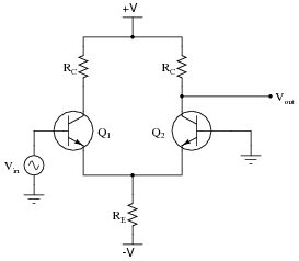
Identify what types of amplifier circuits the two transistors are functioning as (common-collector, common-emitter, common-base) when the differential pair is used like this, and write an equation describing the circuit’s voltage gain. Here is another schematic, showing the transistors modeled as controlled current sources, to help you with the equation:
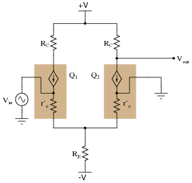
Reveal answerQ1 operates as a common-collector amplifier, while Q2 acts as a common-base amplifier. The gain equation is as such:
$$A_{V(noninvert)}=[\frac{R_C}{r'_e+(r'_e||R_E)}][\frac{r'_e||R_E}{r'_e}]$$
Follow-up question: explain why it is appropriate to simplify the gain equation to this:
$$A_{V(noninvert)}\approx \frac{R_C}{2r'_e}$$
Notes:The purpose of this question is to have students analyze the resistances in the differential pair circuit to develop their own gain equation, based on their understanding of how simpler transistor amplifier circuit gains are derived. Ultimately, this question should lead into another one asking students to express the differential voltage gain of the circuit (a superposition of the gain equations for each input considered separately).
Admittedly, the unsimplified equation shown in the answer is daunting, and students may wonder where I got it. You may help them understand that the basic gain equation for a BJT amplifier is founded on the assumption that IC ≈ IE, that any current through the emitter terminal will be “repeated” at the collector terminal to flow through the collector resistance. Thus, voltage gain is nothing more than a ratio of resistances, given that emitter current and collector current are assumed to be the same:
$$V_{out(AC)} = I_CR_C \ \ \ \ \ \ \ \ \ \ \ \ and \ \ \ \ \ \ \ \ \ \ \ \ V_{in(AC)=I_ER_E}$$
$$...so…$$
$$A_V=\frac{V_{out(AC)}}{V_{in(AC)}}=\frac{I_CR_C}{I_ER_{E(total)}}=\frac{I_CR_C}{I_CR_{E(total)}}=\frac{R_C}{R_{E(total)}}$$
Thus, deriving a gain equation for a BJT amplifier is usually as simple as figuring out what resistance the collector current goes through and dividing that by the amount of resistance the base-to-emitter current has to go through. In a grounded-base amplifier, this ratio is simply \(\frac{R_C}{r'_e}\).
With this circuit, however, the input signal must fight its way through the r′e of Q1 before ever getting to Q2 to be amplified, which is why the voltage gain equation is so much more complex. After going through the dynamic emitter resistance of Q1, it splits between the dynamic emitter resistance of Q2 and the “tail” resistance RE. The term \(r’_e+(r’_e||R_E)\) is the amount of resistance the AC input signal travels through, and the fraction \(\frac{r'_e||R_E}{r'_e}\) defines the splitting of current (most to the emitter of Q2, a small amount through RE)
.