Facebook
 Google
 GitHub
 Linkedin
Digital Circuits
Digital Display Circuits
15 questions By Tony R. Kuphaldt
-
Question 7 of 15
A feature found on most 7-segment decoder/driver ICs is called ripple blanking. Describe what this feature is, and why it is used. Hint: a good source of information on this subject is a datasheet for a 7-segment decoder/driver IC.
Reveal answer“Ripple blanking” is used in multi-digit displays to force leading or trailing zeroes to the off state.
Notes:The answer I give here is purposefully vague, as usual. What I want students to do is research datasheets on their own and be able to show where they got their information.
-
Question 8 of 15
It is usually necessary to have more than one display digit for a digital system. The most obvious and direct way of driving multiple 7-segment display units is to use an equal number of BCD-to-7-segment decoders like this:

If we are driving the decoder ICs with a microprocessor or microcontroller, this direct technique unfortunately uses a lot of I/O pins. In this particular case, with three 7-segment displays, we would need to use twelve output pins on the microcontroller for the three BCD numbers:
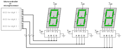
Due to limited pin count on most MPU and MCU chips, I/O lines are precious. It would be a shame to waste so many on a simple function such as driving display digits when we could use them for other tasks such as interfacing with memory devices, receiving real-world data from sensors, driving discrete control devices such as lights and solenoids, or communicating with other MPU/MCU systems. But if each digit requires four output lines for the BCD number, how can we possibly use less than twelve output lines on the processor?
One clever way to do just this exploits persistence of human vision, by driving only one digit at a time. Examine the following circuit, then explain how this “multiplexed” display system works with so few output lines. Also identify what steps the MCU/MPU must take to successfully drive all three digits so the display looks continuous:
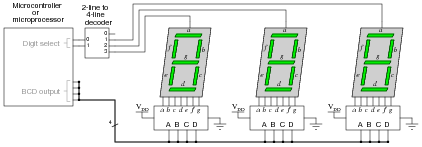
Reveal answerMCU/MPU steps:
- Select digit number 1
- Output BCD code for digit number 1
- Pause for very brief (milliseconds) amount of time
- Select digit number 2
- Output BCD code for digit number 2
- Pause for very brief (milliseconds) amount of time
- Select digit number 3
- Output BCD code for digit number 3
- Pause for very brief (milliseconds) amount of time
- Repeat cycle
Follow-up question: what would have to be changed in this circuit to use common-cathode LED 7-segment displays instead of common-anode displays?
Notes:Be sure to ask your students where they were able to research multiplexed 7-segment displays, and what they think about this particular technique of producing a “continuous” three-digit decimal display by flashing them very rapidly. Clever techniques such as this are often necessary to make the most of limited hardware.
By the way, I have omitted the customary LED current-limiting resistors from the schematic diagrams, for brevity’s sake. See if any of your students are able to catch this omission!
-
Question 9 of 15
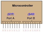
Digital computers communicate with external devices through ports: sets of terminals usually arranged in groups of 4, 8, 16, or more. These terminals may be set to high or low logic states by writing a program for the computer that sends a numerical value to the port. For example, here is an illustration of a microcontroller being instructed to send the hexadecimal number 2B to port A and A9 to port B:
Suppose we wished to use the first seven bits of each port (pins 0 through 6) to drive two 7-segment, common-cathode displays, rather than use BCD-to-7-segment decoder ICs:
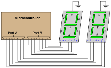
Write the necessary hexadecimal values to be output at ports A and B to generate the display “42” at the two 7-segment display units.
Reveal answerPort A = 5B16 Port B = 6616
Note that the following answers are also valid:
Port A = DB16 Port B = E616
Follow-up question: write these same numerical values in decimal rather than hexadecimal.
Notes:The root of this question is little more than binary-to-hexadecimal conversion, but it also introduces students to the concept of controlling bit states in microcomputer ports by writing hex values. As such, this question is very practical! Although it is unlikely that someone would omit BCD-to-7-segment decoders when building a two-digit decimal display (because doing it this way uses so many more precious microcontroller I/O pins), it is certainly possible! There are many applications other than this where you need to get the microcontroller to output a certain combination of high and low states, and the fastest way to program this is to output hex values to the ports.
In case students ask, let them know that a dollar sign prefix is sometimes used to denote a hexadecimal number. Other times, the prefix 0x is used (e.g., $F3 and 0xF3 mean the same thing).