Facebook
 Google
 GitHub
 Linkedin
Digital Circuits
Digital Display Circuits
15 questions By Tony R. Kuphaldt
-
Question 4 of 15
A seven segment decoder is a digital circuit designed to drive a very common type of digital display device: a set of LED (or LCD) segments that render numerals 0 through 9 at the command of a four-bit code:
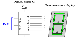
The behavior of the display driver IC may be represented by a truth table with seven outputs: one for each segment of the seven-segment display (a through g). In the following table, a “1” output represents an active display segment, while a “0” output represents an inactive segment:
D C B A a b c d e f g Display
0 0 0 0 1 1 1 1 1 1 0 “0”
0 0 0 1 0 1 1 0 0 0 0 “1”
0 0 1 0 1 1 0 1 1 0 1 “2”
0 0 1 1 1 1 1 1 0 0 1 “3”
0 1 0 0 0 1 1 0 0 1 1 “4”
0 1 0 1 1 0 1 1 0 1 1 “5”
0 1 1 0 1 0 1 1 1 1 1 “6”
0 1 1 1 1 1 1 0 0 0 0 “7”
1 0 0 0 1 1 1 1 1 1 1 “8”
1 0 0 1 1 1 1 1 0 1 1 “9”
Write the unsimplified SOP or POS expressions (choose the most appropriate form) for outputs a, b, c, and e.Reveal answerRaw (unsimplified) expressions:
a = (D + C + B + A)(D + C+ B + A) b = (D + C+ B + A)(D + C+ B+ A) c = D + C B+ A e = DCBA+ DCB A+ DC B A+ D CBAChallenge question: use the laws of Boolean algebra to simplify each of the above expressions into their simplest forms.
Notes:This shows a very practical example of SOP and POS Boolean forms, and why simplification is necessary to reduce the number of required gates to a practical minimum.
-
Question 5 of 15
Examine the datasheet for a 7447 BCD-to-7-segment decoder/driver IC, and identify what input conditions need to be met in order to cause it to display any decimal digit from 0 to 9.
Reveal answerI’ll let you figure out these details by researching the datasheet yourself!
Follow-up question: what features differentiate the 7447 decoder/driver IC from the 7448 or 7449? How about the 74247, 74248, and 74249 decoder/driver circuits? Be prepared to show your sources when answering this question in class.
Notes:Given that datasheets for this particular decoder/driver IC are easy to obtain and read, your students should have no trouble doing the research.
-
Question 6 of 15
Liquid crystal display (LCD) elements require the application of AC voltage rather than DC voltage to prevent certain undesirable effects. Since logic circuits typically operate on DC power (VCC or VDD and Ground), there must be some clever way of generating the necessary AC from DC logic power in order to drive these power-thrifty display devices. Indeed, it just so happens that Exclusive-OR gates do the trick quite nicely:

Consider the square wave voltage source in this schematic as a source of alternating “high” and “low” logic states, 5 volts and 0 volts respectively. Determine what sort of voltage exists across the liquid crystal fluid with the switch in the open position as well as the closed position, and from this determine which switch position results in a darkened LCD versus a transparent LCD.
Reveal answerClosing the switch makes the LCD opaque; opening the switch makes the LCD transparent.
Notes:Note that I did not specify anywhere in the question or in the answer whether the application of voltage across an LCD segment darkened or lightened that segment. This is a detail I leave up to students to research!
The particular method of generating AC from DC using an XOR gate is quite clever. Essentially, we are using the XOR’s ability as a controlled inverter/buffer to reverse “polarity” of the square wave signal. Be sure to have your students explain how AC is applied across the LCD in this circuit.