Facebook
 Google
 GitHub
 Linkedin
Digital Circuits
Digital-to-Analog Conversion
13 questions By Tony R. Kuphaldt
-
Question 4 of 13
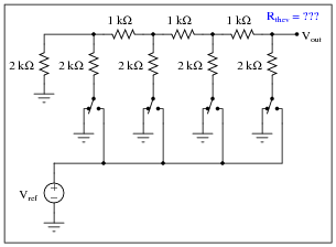
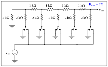
A type of resistor network known as an R-2R ladder is often used in digital-to-analog conversion circuits:
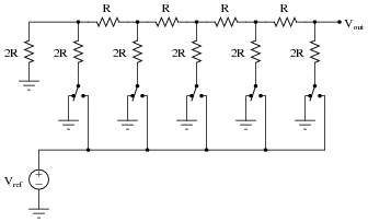
When all switches in the R-2R ladder are in the “ground” position, the network has a very interesting property regardless of its size. Analyze the Thévenin equivalent resistance (as seen from the output terminal) of the following R-2R ladder networks, then comment on the results you obtain:
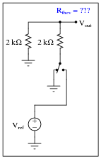
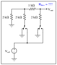
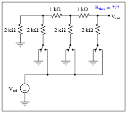
Reveal answerDid you honestly think I’d do all the work for you and just give you the answer?
Notes:The answer is not difficult to obtain if you use each Thévenin equivalent resistance to model the left-hand portion of each successive R-2R ladder network as they become more complex! Those students who do not take this problem-solving step are doomed to perform a lot of series-parallel calculations!
-
Question 5 of 13
When only the most significant bit (MSB) of an R-2R ladder resistor network is activated (all other bits inactive, their switches connecting to ground), the output voltage will be the same, regardless of how many bits the network has:
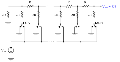
Explain why this output voltage magnitude stands independent of the number of bits (sections) in the R-2R ladder network.
Reveal answerVout = Vref 2Notes:The key to understanding the answer is to apply Thévenin’s theorem to the “inactive” sections of the network. Here, the unique property of constant output impedance for an R-2R network yields a useful feature when applied to DAC circuitry.
-
Question 6 of 13
Thévenin’s theorem is a powerful tool for analyzing R-2R ladder networks. Take for instance this four-section network where the next-to-most-significant “bit” is activated, while all the other “bits” are inactive (switched to ground):
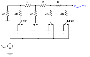
If we Thévenize all sections to the left of the activated section, replacing it with a single resistance to ground, we see the network becomes far simpler:
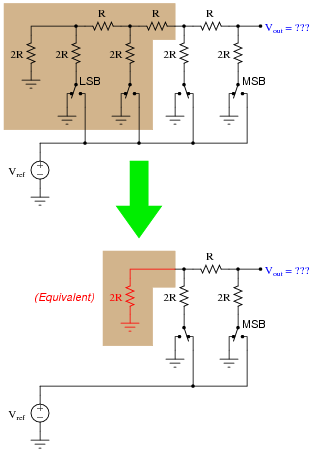
Explain how we may apply Thévenin’s theorem once again to the shaded section of this next circuit (simplified from the previous circuit shown above) to simplify it even more, obtaining a final result for Vout:
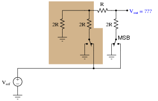
Reveal answerOnce you get to this point, solving for Vout in terms of Vref is trivial:
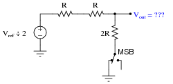
Notes:Students might not realize it is valid to iteratively apply Thévenin’s theorem to the solution of a circuit problem. You can, and this stands as a good example of how (and why!) you should do it.