Facebook
 Google
 GitHub
 Linkedin
Discrete Semiconductor Devices and Circuits
Insulated Gate Field-Effect Transistors
39 questions By Tony R. Kuphaldt
-
Question 28 of 39
Determine whether the load is energized or de-energized with the switch in the position shown. Also, identify whether the transistor is a depletion type or an enhancement type:

Reveal answerThe load will be de-energized as a result of this enhancement-type transistor being in the “off” state.
Notes:Ask your students to explain how they figured out the state of the transistor in this circuit, and also what function the double-pole, double-throw (DPDT) switch performs. Incidentally, this DPDT switch wiring configuration is quite common in electrical and electronic circuits!
-
Question 29 of 39
It is often necessary to have a power transistor source current to a load (provide a path from the positive supply voltage rail to the load) rather than sink current from the load (provide a path from the load to the negative voltage rail or ground), because one side of the load is already connected to ground:
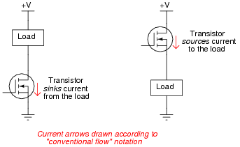
When the transistor sources current, it is often referred to as a high-side switch. Determine the driving voltage requirements for each of these high-side MOSFET switches; that is, determine what must be connected to the gate of each transistor to fully turn it on so that the load receives full power:

Reveal answerFor the P-channel MOSFET, the gate simply needs to be grounded. For the N-channel MOSFET, the gate needs to be brought up to a positive voltage greater than V by at least VGS(on).
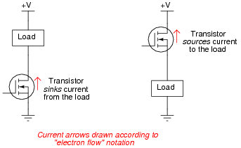
Follow-up question: discuss why the terms “sourcing” and “sinking” make the most sense when viewed from the perspective of conventional flow current notation. For contrast, here is the same circuit with the arrows drawn in the direction of electron flow:
Challenge question: despite the more demanding gate drive requirements of the high-side N-channel MOSFET, these are often preferred over P-channel devices in practical circuit designs. Explain why. Hint: it has something to do with carrier mobility.
Notes:This is a good exercise in determining proper gate voltage polarity (and magnitude), as well as introducing the concepts of current sourcing and sinking, and high-side switching. Be sure to spend time discussing the matter of sourcing versus sinking, as this will be of greater importance later in your students’ studies (especially in logic gate circuit design).
-
Question 30 of 39
Draw the proper wire connections necessary for “enhancing” this MOSFET with the solar cell’s voltage, so that the battery energizes the relay whenever there is sufficient light exposure on the solar cell:

Reveal answer
Challenge question: connect a commutating (“free-wheeling”) diode into the circuit shown, so that inductive “kickback” from the relay de-energizing does not harm the MOSFET.
Notes:Students should note that the circuit shown is not the only possible way a MOSFET could be used to turn a relay on. Often, the substrate (SS) and source (S) terminals of the MOSFET are made common with each other, so that the controlling and controlled circuits share a common point (usually the system “ground” point).
Ask your students what would happen if the battery’s polarity were reversed.