Facebook
 Google
 GitHub
 Linkedin
Analog Integrated Circuits
Inverting and Noninverting OpAmp Voltage Amplifier Circuits
41 questions By Tony R. Kuphaldt
-
Question 7 of 41
Calculate all voltage drops and currents in this circuit, complete with arrows for current direction and polarity markings for voltage polarity. Then, calculate the overall voltage gain of this amplifier circuit (AV), both as a ratio and as a figure in units of decibels (dB):

Reveal answer
AV = 1.468 = 3.335 dB
Notes:Operational amplifier circuits provide a great opportunity to review basic concepts of DC circuits: voltage drops, polarity, current directions, Ohm’s Law, Kirchhoff’s Voltage Law, Kirchhoff’s Current Law, etc. This circuit is no exception. Emphasize the fact that a great many opamp circuits may be comprehensively analyzed merely with knowledge of these fundamental principles and the characteristics of an ideal opamp (zero input current, infinite open-loop gain, unlimited output voltage swing, zero voltage between input terminals when negative feedback is in effect).
Some students may arrive at the wrong gain figure because they blindly followed a formula with R1 and R2 shown as variables, plugging in this circuit’s values for R1 and R2 without considering which resistor is which (is R1 the feedback resistor or is R2?). This is by design, as I want students to learn to think about what they are doing rather than thoughtlessly follow instructions.
-
Question 8 of 41
Calculate all voltage drops and currents in this circuit, complete with arrows for current direction and polarity markings for voltage polarity. Then, calculate the overall voltage gain of this amplifier circuit (AV), both as a ratio and as a figure in units of decibels (dB):

Reveal answer
AV = 4.704 = 13.449 dB
Follow-up question: how much input impedance does the -2.35 volt source “see” as it drives this amplifier circuit?
Notes:Operational amplifier circuits provide a great opportunity to review basic concepts of DC circuits: voltage drops, polarity, current directions, Ohm’s Law, Kirchhoff’s Voltage Law, Kirchhoff’s Current Law, etc. This circuit is no exception. Emphasize the fact that a great many opamp circuits may be comprehensively analyzed merely with knowledge of these fundamental principles and the characteristics of an ideal opamp (zero input current, infinite open-loop gain, unlimited output voltage swing, zero voltage between input terminals when negative feedback is in effect).
The follow-up question is important because it showcases one of the great advantages of using non-inverting opamp amplifier circuits as voltage signal amplifiers: extremely high input impedance. This would be a good opportunity to review typical input impedance values for operational amplifiers, by showing datasheets for some typical opamps and for some non-typical (i.e. MOSFET input) opamps.
-
Question 9 of 41
Determine both the input and output voltage in this circuit:
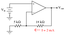
Reveal answerVin = 10 V Vout = 46 V
Notes:Ask your students how they solved this problem, sharing techniques and strategies to help other students know where to begin and where to proceed from there.