Facebook
 Google
 GitHub
 Linkedin
Analog Integrated Circuits
Inverting and Noninverting OpAmp Voltage Amplifier Circuits
41 questions By Tony R. Kuphaldt
-
Question 16 of 41
Calculate the voltage gain for each stage of this amplifier circuit (both as a ratio and in units of decibels), then calculate the overall voltage gain:
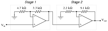
Reveal answer- Stage 1:
- AV = 1.702 = 4.62 dB
- Stage 2:
- AV = 5.136 = 14.213 dB
- Overall:
- AV = 8.743 = 18.833 dB
Notes:Not only does this question review calculation of voltage gain for inverting amplifier circuits, but it also reviews decibel calculations (for both single and multi-stage amplifiers). Discuss how the decibel figures for each stage add to equal the total decibel gain, whereas the ratios multiply.
-
Question 17 of 41
How much effect will a change in the op-amp’s open-loop voltage gain have on the overall voltage gain of a negative-feedback circuit such as this?
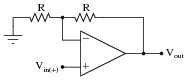
If the open-loop gain of this operational amplifier were to change from 100,000 to 200,000, for example, how big of an effect would it have on the voltage gain as measured from the non-inverting input to the output?
Reveal answerThe different in overall voltage gain will be trivial.
Follow-up question: what advantage is there in building voltage amplifier circuits in this manner, applying negative feedback to a “core” amplifier with very high intrinsic gain?
Notes:Work with your students to calculate a few example scenarios, with the old open-loop gain versus the new open-loop gain. Have the students validate their conclusions with numbers!
Negative feedback is an extremely useful engineering principle, and one that allows us to build very precise amplifiers using imprecise components. Credit for this idea goes to Harold Black, an electrical engineer, in 1920’s. Mr. Black was looking for a way to improve the linearity and stability of amplifiers in telephone systems, and (as legend has it) the idea came to him in a flash of insight as he was commuting on a ferry boat.
An interesting historical side-note is that Black’s 1928 patent application was initially rejected on the grounds that he was trying to submit a perpetual motion device! The concept of negative feedback in an amplifier circuit was so contrary to established engineering thought at the time, that Black experienced significant resistance to the idea within the engineering community. The United States patent office, on the other hand, was inundated with fraudulent “perpetual motion” claims, and so dismissed Black’s invention at first sight.
-
Question 18 of 41
Suppose a technician is checking the operation of the following electronic circuit:
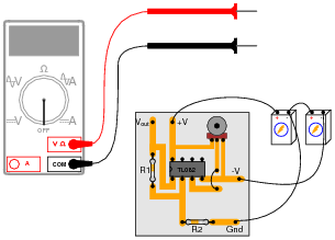
She decides to measure the voltage on either side of resistor R1 with reference to ground, and obtains these readings:
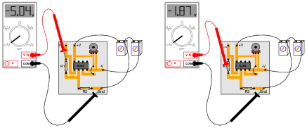
On the top side of R1, the voltage with reference to ground is -5.04 volts. On the bottom side of R1, the voltage with reference to ground is -1.87 volts. The color code of resistor R1 is Yellow, Violet, Orange, Gold. From this information, determine the following:
- Voltage across R1 (between top to bottom):
- Polarity ( and -) of voltage across R1:
- Current (magnitude) through R1:
- Direction of current through R1:
Additionally, explain how this technician would make each one of these determinations. What rules or laws of electric circuits would she apply?
Reveal answer- Voltage across R1 (between top to bottom): 3.17 volts
- Polarity ( and -) of voltage across R1: (-) on top, ( ) on bottom
- Current (magnitude) through R1: 67.45 μA
- Direction of current through R1: upward, following conventional flow
Follow-up question: calculate the range of possible currents, given the specified tolerance of resistor R1 (67.45 μA assumes 0% error).
Challenge question: if you recognize the type of circuit this is (by the part number of the IC “chip”: TL082), identify the voltage between pin 3 and ground.
Notes:This is a good example of how Kirchhoff’s Voltage Law is more than just an abstract tool for mathematical analysis - it is also a powerful technique for practical circuit diagnosis. Students must apply KVL to determine the voltage drop across R1, and then use Ohm’s Law to calculate its current.
If students experience difficulty visualizing how KVL plays a part in the solution of this problem, show them this illustration:

By the way, the answer to the challenge question may only be realized if students recognize this circuit as a non-inverting opamp voltage amplifier. The voltage at pin 3 (non-inverting input) will be the same as the voltage at pin 2 (inverting input): -1.87 volts.