Facebook
 Google
 GitHub
 Linkedin
Analog Integrated Circuits
Inverting and Noninverting OpAmp Voltage Amplifier Circuits
41 questions By Tony R. Kuphaldt
-
Question 19 of 41
Trace the directions for all currents in this circuit, and calculate the values for voltage at the output (Vout) and at test point 1 (VTP1) for several values of input voltage (Vin):
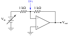
Vin VTP1 Vout
0.0 V
0.4 V
1.2 V
3.4 V
7.1 V
10.8 V
Then, from the table of calculated values, determine the voltage gain (AV) for this amplifier circuit.Reveal answer
Vin VTP1 Vout
0.0 V 0.0 V 0.0 V
0.4 V 0.0 V -0.4 V
1.2 V 0.0 V -1.2 V
3.4 V 0.0 V -3.4 V
7.1 V 0.0 V -7.1 V
10.8 V 0.0 V -10.8 V
AV = 1 (ratio) = 0 dB Follow-up question: the point marked “TP1” in this circuit is often referred to as a virtual ground. Explain why this is, based on the voltage figures shown in the above table.
Notes:Some texts describe the voltage gain of an inverting voltage amplifier as being a negative quantity. I tend not to look at things that way, treating all gains as positive quantities and relying on my knowledge of circuit behavior to tell whether the signal is inverted or not. In my teaching experience, I have found that students have a tendency to blindly follow equations rather than think about what it is they are calculating, and that strict adherence to the mathematical signs of gain values only encourages this undesirable behavior (Ïf the sign of the gain tells me whether the circuit is inverting or not, I can just multiply input voltage by gain and the answer will always be right!”).
This strategy is analogous to problem-solving in electromagnetics, where a common approach is to use math to solve for the absolute values of quantities (potential, induced voltage, magnetic flux), and then to use knowledge of physical principles (Lenz’ Law, right-hand rule) to solve for polarities and directions. The alternative - to try to maintain proper sign convention throughout all calculations - not only complicates the math but it also encourages students to over-focus on calculations and neglect fundamental principles.
-
Question 20 of 41
Calculate the overall voltage gain of this amplifier circuit (AV), both as a ratio and as a figure in units of decibels (dB). Also, write a general equation for calculating the voltage gain of such an amplifier, given the resistor values of R1 and R2:

Reveal answerAV = 1 = 0 dB
AV = R1 R2(expressed as a ratio, not dB) Follow-up question #1: sometimes the voltage gain equation for an amplifier of this type is given in the following form:
AV = − R1 R2What is the significance of the negative sign in this equation? Is it really necessary, or does it communicate an important concept?
Follow-up question #2: manipulate the gain equation for this amplifier circuit to solve for the value of resistor R1.
Notes:Whether inverting amplifier gains are expressed as negative or positive quantities seems to be a matter of taste, from surveying introductory textbooks on the subject. I prefer to stick with absolute (positive) gain values and consider signal inversion separately.
-
Question 21 of 41
Calculate all voltage drops and currents in this circuit, complete with arrows for current direction and polarity markings for voltage polarity. Then, calculate the overall voltage gain of this amplifier circuit (AV), both as a ratio and as a figure in units of decibels (dB):

Reveal answer
AV = 0.468 = -6.594 dB
Notes:Operational amplifier circuits provide a great opportunity to review basic concepts of DC circuits: voltage drops, polarity, current directions, Ohm’s Law, Kirchhoff’s Voltage Law, Kirchhoff’s Current Law, etc. This circuit is no exception. Emphasize the fact that a great many opamp circuits may be comprehensively analyzed merely with knowledge of these fundamental principles and the characteristics of an ideal opamp (zero input current, infinite open-loop gain, unlimited output voltage swing, zero voltage between input terminals when negative feedback is in effect).
Some students may arrive at the wrong gain figure because they blindly followed a formula with R1 and R2 shown as variables, plugging in this circuit’s values for R1 and R2 without considering which resistor is which (is R1 the feedback resistor or is R2?). This is by design, as I want students to learn to think about what they are doing rather than thoughtlessly follow instructions.