Facebook
 Google
 GitHub
 Linkedin
AC Electric Circuits
Mixed-Frequency Signals
31 questions By Tony R. Kuphaldt
-
Question 13 of 31
The Fourier series for a square wave is as follows:
vsquare = 4 πVm ( sinωt + 1 3sin3 ωt + 1 5sin5 ωt + 1 7sin7 ωt … + 1 n+ sinn ωt ) Where,
Vm = Peak amplitude of square wave
ω = Angular velocity of square wave (equal to 2 πf, where f is the fundamental frequency)
n = An odd integer
Electrically, we might represent a square-wave voltage source as a circle with a square-wave symbol inside, like this:

Knowing the Fourier series of this voltage, however, allows us to represent the same voltage source as a set of series-connected voltage sources, each with its own (sinusoidal) frequency. Draw the equivalent schematic for a 10 volt (peak), 200 Hz square-wave source in this manner showing only the first four harmonics, labeling each sinusoidal voltage source with its own RMS voltage value and frequency:
Hint: ω = 2 πf
Reveal answer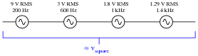
Notes:To be honest, the four-harmonic equivalent circuit is a rather poor approximation for a square wave. The real purpose of this question, though, is to have students relate the sinusoidal terms of a common Fourier series (for a square wave) to a schematic diagram, translating between angular velocity and frequency, peak values and RMS values.
Please note that the voltage magnitudes shown in the answer are RMS and not peak! If you were to calculate peak sinusoid source values, you would obtain these results:
- 1st harmonic: [40/(π)] volts peak = 12.73 volts peak
- 3rd harmonic: [40/(3 π)] volts peak = 4.244 volts peak
- 5th harmonic: [40/(5 π)] volts peak = 2.546 volts peak
- 7th harmonic: [40/(7 π)] volts peak = 1.819 volts peak
-
Question 14 of 31
Suppose a non-sinusoidal voltage source is represented by the following Fourier series:
v(t) = 23.2 + 30 sin(377t) + 15.5 sin(1131t + 90) + 2.7 sin(1508t - 40) Electrically, we might represent this non-sinusoidal voltage source as a circle, like this:

Knowing the Fourier series of this voltage, however, allows us to represent the same voltage source as a set of series-connected voltage sources, each with its own (sinusoidal) frequency. Draw the equivalent schematic in this manner, labeling each voltage source with its RMS voltage value, frequency (in Hz), and phase angle:
Hint: ω = 2 πf
Reveal answer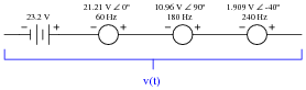
Notes:The purpose of this question is to have students relate the sinusoidal terms of a particular Fourier series to a schematic diagram, translating between angular velocity and frequency, peak values and RMS values.
-
Question 15 of 31
Calculate the power dissipated by a 25 Ω resistor, when powered by a square-wave with a symmetrical amplitude of 100 volts and a frequency of 2 kHz:
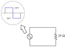
Reveal answerPR = 400 watts
Notes:To calculate this power figure, students have to determine the RMS value of the square wave. Thankfully, this is not difficult.


Related Tools:
- Intermediate Electromagnetism and Electromagnetic Induction
- Performance-Based Assessments for Network Analysis Competencies