Facebook
 Google
 GitHub
 Linkedin
AC Electric Circuits
Mixed-Frequency Signals
31 questions By Tony R. Kuphaldt
-
Question 16 of 31
Calculate the power dissipated by a 25 Ω resistor, when powered by a square-wave with a symmetrical amplitude of 100 volts and a frequency of 2 kHz, through a 0.22 μF capacitor:

No, I’m not asking you to calculate an infinite number of terms in the Fourier series - that would be cruel and unusual. Just calculate the power dissipated in the resistor by the 1st, 3rd, 5th, and 7th harmonics only.
Reveal answerPR(1st) = 1.541 watts
PR(3rd) = 1.485 watts
PR(5th) = 1.384 watts
PR(7th) = 1.255 watts
PR(1 3 5 7) = 5.665 watts
Notes:To calculate this power figure, students have to research the Fourier series for a square wave. Many textbooks use square waves to introduce the subject of Fourier series, so this should not be difficult for students to find.
Ask your students how the real power dissipated by this resistor compares with the final figure of 5.665 watts. Is the real power dissipation more, less, or equal to this figure? If not equal, what would we have to do to arrive at a more precise figure?
-
Question 17 of 31
Ideally, a sinusoidal oscillator will output a signal consisting of a single (fundamental) frequency, with no harmonics. Realistically, though, sine-wave oscillators always exhibit some degree of distortion, and are therefore never completely harmonic-free.
Describe what the display of a spectrum analyzer would look like when connected to the output of a perfect sinusoidal oscillator. Then, describe what the same instrument’s display would look like if the oscillator exhibited substantial distortion.
Reveal answerI’ll let you figure out the answer to this question on your own.
Notes:The purpose of this question is to get students to think about how a spectrum analyzer would be used in a practical scenario, and what the spectrum would look like for a couple of different scenarios. Really, it focuses more on the harmonic analysis instrument (the spectrum analyzer) more than the oscillator circuit.
-
Question 18 of 31
An electronics technician connects the input of a spectrum analyzer to the secondary winding of an AC power transformer, plugged into a power receptacle. He sets the spectrum analyzer to show 60 Hz as the fundamental frequency, expecting to see the following display:
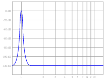
Instead, however, the spectrum analyzer shows more than just a single peak at the fundamental:
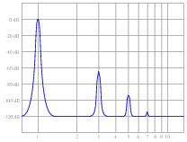
Explain what this pattern means, in practical terms. Why is this power system’s harmonic signature different from what the technician expected to see?
Reveal answerWhat this pattern means is the power-line voltage waveform is distorted from what should be a perfect sine-wave shape.
Notes:Note to your students that this is quite typical for modern power systems, due to the prevalence of switching power supply circuits and other “non-linear” electrical loads. The presence of harmonic frequencies in significant quantity can cause severe problems for power systems, including transformer overheating, motor overheating, overloaded neutral conductors (especially in three-phase, four-wire “Wye” systems), and excessive currents through power-factor correction capacitors.
Related Tools:
- Intermediate Electromagnetism and Electromagnetic Induction
- Performance-Based Assessments for Network Analysis Competencies