Facebook
 Google
 GitHub
 Linkedin
AC Electric Circuits
Capacitive Reactance
-
Question 1
Don’t just sit there! Build something!! Learning to mathematically analyze circuits requires much study and practice. Typically, students practice by working through lots of sample problems and checking their answers against those provided by the textbook or the instructor. While this is good, there is a much better way.
You will learn much more by actually building and analyzing real circuits, letting your test equipment provide the “answers” instead of a book or another person. For successful circuit-building exercises, follow these steps:
- Carefully measure and record all component values prior to circuit construction.
- Draw the schematic diagram for the circuit to be analyzed.
- Carefully build this circuit on a breadboard or other convenient medium.
- Check the accuracy of the circuit’s construction, following each wire to each connection point, and verifying these elements one-by-one on the diagram.
- Mathematically analyze the circuit, solving for all voltage and current values.
- Carefully measure all voltages and currents, to verify the accuracy of your analysis.
- If there are any substantial errors (greater than a few percent), carefully check your circuit’s construction against the diagram, then carefully re-calculate the values and re-measure.
For AC circuits where inductive and capacitive reactances (impedances) are a significant element in the calculations, I recommend high quality (high-Q) inductors and capacitors, and powering your circuit with low frequency voltage (power-line frequency works well) to minimize parasitic effects. If you are on a restricted budget, I have found that inexpensive electronic musical keyboards serve well as “function generators” for producing a wide range of audio-frequency AC signals. Be sure to choose a keyboard “voice” that closely mimics a sine wave (the “panflute” voice is typically good), if sinusoidal waveforms are an important assumption in your calculations.
As usual, avoid very high and very low resistor values, to avoid measurement errors caused by meter “loading”. I recommend resistor values between 1 kΩ and 100 kΩ.
One way you can save time and reduce the possibility of error is to begin with a very simple circuit and incrementally add components to increase its complexity after each analysis, rather than building a whole new circuit for each practice problem. Another time-saving technique is to re-use the same components in a variety of different circuit configurations. This way, you won’t have to measure any component’s value more than once.
Reveal answerLet the electrons themselves give you the answers to your own “practice problems”!
Notes:It has been my experience that students require much practice with circuit analysis to become proficient. To this end, instructors usually provide their students with lots of practice problems to work through, and provide answers for students to check their work against. While this approach makes students proficient in circuit theory, it fails to fully educate them.
Students don’t just need mathematical practice. They also need real, hands-on practice building circuits and using test equipment. So, I suggest the following alternative approach: students should build their own “practice problems” with real components, and try to mathematically predict the various voltage and current values. This way, the mathematical theory “comes alive,” and students gain practical proficiency they wouldn’t gain merely by solving equations.
Another reason for following this method of practice is to teach students scientific method: the process of testing a hypothesis (in this case, mathematical predictions) by performing a real experiment. Students will also develop real troubleshooting skills as they occasionally make circuit construction errors.
Spend a few moments of time with your class to review some of the “rules” for building circuits before they begin. Discuss these issues with your students in the same Socratic manner you would normally discuss the worksheet questions, rather than simply telling them what they should and should not do. I never cease to be amazed at how poorly students grasp instructions when presented in a typical lecture (instructor monologue) format!
An excellent way to introduce students to the mathematical analysis of real circuits is to have them first determine component values (L and C) from measurements of AC voltage and current. The simplest circuit, of course, is a single component connected to a power source! Not only will this teach students how to set up AC circuits properly and safely, but it will also teach them how to measure capacitance and inductance without specialized test equipment.
A note on reactive components: use high-quality capacitors and inductors, and try to use low frequencies for the power supply. Small step-down power transformers work well for inductors (at least two inductors in one package!), so long as the voltage applied to any transformer winding is less than that transformer’s rated voltage for that winding (in order to avoid saturation of the core).
A note to those instructors who may complain about the “wasted” time required to have students build real circuits instead of just mathematically analyzing theoretical circuits:
What is the purpose of students taking your course?
If your students will be working with real circuits, then they should learn on real circuits whenever possible. If your goal is to educate theoretical physicists, then stick with abstract analysis, by all means! But most of us plan for our students to do something in the real world with the education we give them. The “wasted” time spent building real circuits will pay huge dividends when it comes time for them to apply their knowledge to practical problems.
Furthermore, having students build their own practice problems teaches them how to perform primary research, thus empowering them to continue their electrical/electronics education autonomously.
In most sciences, realistic experiments are much more difficult and expensive to set up than electrical circuits. Nuclear physics, biology, geology, and chemistry professors would just love to be able to have their students apply advanced mathematics to real experiments posing no safety hazard and costing less than a textbook. They can’t, but you can. Exploit the convenience inherent to your science, and get those students of yours practicing their math on lots of real circuits!
-
Question 2
As a general rule, capacitors oppose change in (choose: voltage or current), and they do so by . . . (complete the sentence).
Based on this rule, determine how a capacitor would react to a constant AC voltage that increases in frequency. Would an capacitor pass more or less current, given a greater frequency? Explain your answer.
Reveal answerAs a general rule, capacitors oppose change in voltage, and they do so by producing a current.
A capacitor will pass a greater amount of AC current, given the same AC voltage, at a greater frequency.
Notes:This question is an exercise in qualitative thinking: relating rates of change to other variables, without the use of numerical quantities. The general rule stated here is very, very important for students to master, and be able to apply to a variety of circumstances. If they learn nothing about capacitors except for this rule, they will be able to grasp the function of a great many capacitor circuits.
-
Question 3
∫f(x) dx Calculus alert!
We know that the formula relating instantaneous voltage and current in a capacitor is this:i = C de dtKnowing this, determine at what points on this sine wave plot for capacitor voltage is the capacitor current equal to zero, and where the current is at its positive and negative peaks. Then, connect these points to draw the waveform for capacitor current:
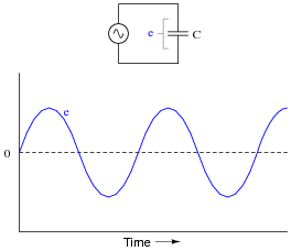
How much phase shift (in degrees) is there between the voltage and current waveforms? Which waveform is leading and which waveform is lagging?
Reveal answer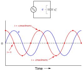
For a capacitor, voltage is lagging and current is leading, by a phase shift of 90o.
Notes:This question is an excellent application of the calculus concept of the derivative: relating one function (instantaneous current, i) with the instantaneous rate-of-change of another function (voltage, [de/dt]).
-
Question 4
You should know that a capacitor is formed by two conductive plates separated by an electrically insulating material. As such, there is no “ohmic” path for electrons to flow between the plates. This may be vindicated by an ohmmeter measurement, which tells us a capacitor has (nearly) infinite resistance once it is charged to the ohmmeter’s full output voltage.
Explain then, how a capacitor is able to continuously pass alternating current, even though it cannot continuously pass DC.
Reveal answerI’ll let you figure this out on your own!
Notes:This feature of capacitors is extremely useful in electronic circuitry. Your students will find many applications of it later on in their studies!
-
Question 5
Does a capacitor’s opposition to alternating current increase or decrease as the frequency of that current increases? Also, explain why we refer to this opposition of AC current in a capacitor as reactance instead of resistance.
Reveal answerThe opposition to AC current (“reactance”) of a capacitor decreases as frequency increases. We refer to this opposition as “reactance” rather than “resistance” because it is non-dissipative in nature. In other words, reactance causes no power to leave the circuit.
Notes:Ask your students to define the relationship between capacitor reactance and frequency as either “directly proportional” or “inversely proportional”. These are two phrases used often in science and engineering to describe whether one quantity increases or decreases as another quantity increases. Your students definitely need to be familiar with both these phrases, and be able to interpret and use them in their technical discussions.
Also, discuss the meaning of the word “non-dissipative” in this context. How could we prove that the opposition to current expressed by a capacitor is non-dissipative? What would be the ultimate test of this?
-
Question 6
Will the current through the resistor increase or decrease as the capacitor plates are moved closer together?
Explain why this happens, with reference to capacitive reactance (XC).
Reveal answerThe current will increase.
Follow-up question: combine the physical capacitance equation and the capacitive reactance equation together to form a new equation that solves for reactance (XC) given all the physical specifications of the capacitor (plate area, spacing, and permittivity) and the applied frequency:
C = εA dXC = 1 2 πf CNotes:Students might be able to guess the correct answer even if they know nothing about capacitive reactance, just by assuming that closer plates means a more complete circuit. The real answer is more complex than this, though, and that is what you must draw out of the discussion with them.
-
Question 7
Suppose someone were to ask you to differentiate electrical reactance (X) from electrical resistance (R). How would you distinguish these two similar concepts from one another, using your own words?
Reveal answerIt is really important for you to frame this concept in your own words, so be sure to check with your instructor on the accuracy of your answer to this question! To give you a place to start, I offer this distinction: resistance is electrical friction, whereas reactance is electrical energy storage. Fundamentally, the difference between X and R is a matter of energy exchange, and it is understood most accurately in those terms.
Notes:This is an excellent point of crossover with your students’ studies in elementary physics, if they are studying physics now or have studied physics in the past. The energy-storing actions of inductors and capacitors are quite analogous to the energy-storing actions of masses and springs (respectively, if you associate velocity with current and force with voltage). In the same vein, resistance is analogous to kinetic friction between a moving object and a stationary surface. The parallels are so accurate, in fact, that the electrical properties of R, L, and C have been exploited to model mechanical systems of friction, mass, and resilience in circuits known as analog computers.
-
Question 8
A capacitor rated at 2.2 microfarads is subjected to a sinusoidal AC voltage of 24 volts RMS, at a frequency of 60 hertz. Write the formula for calculating capacitive reactance (XC), and solve for current through the capacitor.
Reveal answerXC = 1 2 πf CThe current through this capacitor is 19.91 mA RMS.
Notes:I have consistently found that qualitative (greater than, less than, or equal) analysis is much more difficult for students to perform than quantitative (punch the numbers on a calculator) analysis. Yet, I have consistently found on the job that people lacking qualitative skills make more “silly” quantitative errors because they cannot validate their calculations by estimation.
In light of this, I always challenge my students to qualitatively analyze formulae when they are first introduced to them. Ask your students to identify what will happen to one term of an equation if another term were to either increase, or decrease (you choose the direction of change). Use up and down arrow symbols if necessary to communicate these changes graphically. Your students will greatly benefit in their conceptual understanding of applied mathematics from this kind of practice!
-
Question 9
At what frequency does a 33 μF capacitor have 20 Ω of reactance? Write the formula for solving this, in addition to calculating the frequency.
Reveal answerf = 241.1 Hz
Notes:Be sure to ask your students to demonstrate the algebraic manipulation of the original formula, in providing the answer to this question. Algebraic manipulation of equations is a very important skill to have, and it comes only by study and practice.
-
Question 10
Explain all the steps necessary to calculate the amount of current in this capacitive AC circuit:
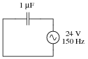
Reveal answerI = 22.6 mA
Notes:The current is not difficult to calculate, so obviously the most important aspect of this question is not the math. Rather, it is the procedure of calculation: what to do first, second, third, etc., in obtaining the final answer.
-
Question 11
In DC circuits, we have Ohm’s Law to relate voltage, current, and resistance together:
E = I R In AC circuits, we similarly need a formula to relate voltage, current, and impedance together. Write three equations, one solving for each of these three variables: a set of Ohm’s Law formulae for AC circuits. Be prepared to show how you may use algebra to manipulate one of these equations into the other two forms.
Reveal answerE = I Z I = E ZZ = E IIf using phasor quantities (complex numbers) for voltage, current, and impedance, the proper way to write these equations is as follows:
E = IZ I = E ZZ = E IBold-faced type is a common way of denoting vector quantities in mathematics.
Notes:Although the use of phasor quantities for voltage, current, and impedance in the AC form of Ohm’s Law yields certain distinct advantages over scalar calculations, this does not mean one cannot use scalar quantities. Often it is appropriate to express an AC voltage, current, or impedance as a simple scalar number.
-
Question 12
It is often necessary to represent AC circuit quantities as complex numbers rather than as scalar numbers, because both magnitude and phase angle are necessary to consider in certain calculations.
When representing AC voltages and currents in polar form, the angle given refers to the phase shift between the given voltage or current, and a “reference” voltage or current at the same frequency somewhere else in the circuit. So, a voltage of 3.5 V ∠−45o means a voltage of 3.5 volts magnitude, phase-shifted 45 degrees behind (lagging) the reference voltage (or current), which is defined to be at an angle of 0 degrees.
But what about impedance (Z)? Does impedance have a phase angle, too, or is it a simple scalar number like resistance or reactance?
Calculate the amount of current that would go “through” a 0.1 μF capacitor with 48 volts RMS applied to it at a frequency of 100 Hz. Then, based on Ohm’s Law for AC circuits and what you know of the phase relationship between voltage and current for a capacitor, calculate the impedance of this capacitor in polar form. Does a definite angle emerge from this calculation for the capacitor’s impedance? Explain why or why not.
Reveal answerZC = 15.92 kΩ ∠ -90o
Notes:This is a challenging question, because it asks the student to defend the application of phase angles to a type of quantity that does not really possess a wave-shape like AC voltages and currents do. Conceptually, this is difficult to grasp. However, the answer is quite clear through the Ohm’s Law calculation (Z = E/I).
Although it is natural to assign a phase angle of 0o to the 48 volt supply, making it the reference waveform, this is not actually necessary. Work through this calculation with your students, assuming different angles for the voltage in each instance. You should find that the impedance computes to be the same exact quantity every time.
-
Question 13
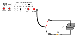
Explain how you could calculate the capacitance value of a capacitor (in units of Farads), by measuring AC voltage, AC current, and frequency in a circuit of this configuration:
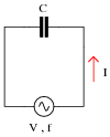
Write a single formula solving for capacitance given these three values (V, I, and f).
Reveal answerC = I 2 πf VNotes:Ask your students to show how they arrived at the formula for calculating C. The algebra is not difficult, but some substitution is required.
-
Question 14
A technician measures voltage across the terminals of a burned-out solenoid valve, in order to check for the presence of dangerous voltage before touching the wire connections. The circuit breaker for this solenoid has been turned off and secured with a lock, but the technician’s digital voltmeter still registers about three and a half volts AC across the solenoid terminals!
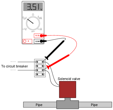
Now, three and a half volts AC is not enough voltage to cause any harm, but its presence confuses and worries the technician. Shouldn’t there be 0 volts, with the breaker turned off?
Explain why the technician is able to measure voltage in a circuit that has been “locked out.” Hint: digital voltmeters have extremely high input impedance, typically in excess of 10 MΩ.
Reveal answerThe stray capacitance existing between the open contacts of the breaker provides a high-impedance path for AC voltage to reach the voltmeter test leads.
Follow-up question: while the measured voltage in this case was well below the general industry threshold for shock hazard (30 volts), a slightly different scenario could have resulted in a much greater “phantom” voltage measurement. Could a capacitively-coupled voltage of this sort possibly pose a safety hazard? Why or why not?
Challenge question: is it possible for the technician to discern whether or not the 3.51 volts measured by the voltmeter is “real”? In other words, what if this small voltage is not the result of stray capacitance across the breaker contacts, but rather some other source of AC capable of delivering substantial current? How can the technician determine whether or not the 3.51 volts is capable of sourcing significant amounts of current?
Notes:I cannot tell you how many times I encountered this phenomenon: “phantom” AC voltages registered by high-impedance DMM’s in circuits that are supposed to be “dead.” Industrial electricians often use a different instrument to check for the presence of dangerous voltage, a crude device commonly known as a “Wiggy.”
-
Question 15
Audio headphones make highly sensitive voltage detectors for AC signals in the audio frequency range. However, the small speakers inside headphones are quite easily damaged by the application of DC voltage.
Explain how a capacitor could be used as a “filtering” device to allow AC signals through to a pair of headphones, yet block any applied DC voltage, so as to help prevent accidental damage of the headphones while using them as an electrical instrument.
The key to understanding how to answer this question is to recognize what a capacitor “appears as” to AC signals versus DC signals.
Reveal answerConnect a capacitor in series with the headphone speakers.
Notes:I highly recommend to students that they should build a transformer-isolation circuit if they intend to use a pair of audio headphones as a test device (see question file number 00983 for a complete schematic diagram).