Facebook
 Google
 GitHub
 Linkedin
AC Capacitor Circuits
Capacitors Vs. Resistors
Capacitors do not behave the same as resistors. Whereas resistors allow a flow of electrons through them directly proportional to the voltage drop, capacitors oppose changes in voltage by drawing or supplying current as they charge or discharge to the new voltage level.
The flow of electrons “through” a capacitor is directly proportional to the rate of change of voltage across the capacitor. This opposition to voltage change is another form of reactance, but one that is precisely opposite to the kind exhibited by inductors.
Capacitor Circuit Characteristics
Expressed mathematically, the relationship between the current “through” the capacitor and rate of voltage change across the capacitor is as such:
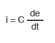
The expression de/dt is one from calculus, meaning the rate of change of instantaneous voltage (e) over time, in volts per second. The capacitance (C) is in Farads, and the instantaneous current (i), of course, is in amps.
Sometimes you will find the rate of instantaneous voltage change over time expressed as dv/dt instead of de/dt: using the lower-case letter “v” instead or “e” to represent voltage, but it means the exact same thing. To show what happens with alternating current, let’s analyze a simple capacitor circuit:
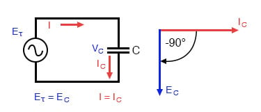
Pure capacitive circuit: capacitor voltage lags capacitor current by 90°
If we were to plot the current and voltage for this very simple circuit, it would look something like this:
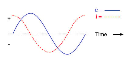
Pure capacitive circuit waveforms.
Remember, the current through a capacitor is a reaction against the change in voltage across it.
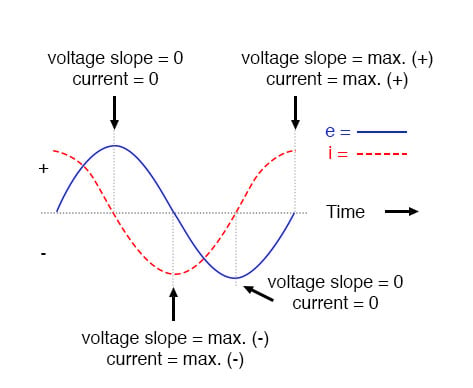
Therefore, the instantaneous current is zero whenever the instantaneous voltage is at a peak (zero change, or level slope, on the voltage sine wave), and the instantaneous current is at a peak wherever the instantaneous voltage is at maximum change (the points of steepest slope on the voltage wave, where it crosses the zero line).
This results in a voltage wave that is -90° out of phase with the current wave. Looking at the graph, the current wave seems to have a “head start” on the voltage wave; the current “leads” the voltage, and the voltage “lags” behind the current.
Voltage lags current by 90° in a pure capacitive circuit.
As you might have guessed, the same unusual power wave that we saw with the simple inductor circuit is present in the simple capacitor circuit, too:
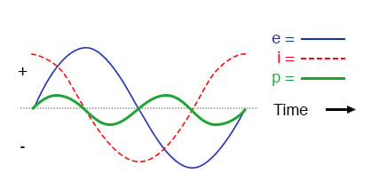
In a pure capacitive circuit, the instantaneous power may be positive or negative.
As with the simple inductor circuit, the 90-degree phase shift between voltage and current results in a power wave that alternates equally between positive and negative. This means that a capacitor does not dissipate power as it reacts against changes in voltage; it merely absorbs and releases power, alternately.
A Capacitor’s Reactance
A capacitor’s opposition to change in voltage translates to an opposition to alternating voltage in general, which is by definition always changing in instantaneous magnitude and direction.
For any given magnitude of AC voltage at a given frequency, a capacitor of given size will “conduct” a certain magnitude of AC current.
Just as the current through a resistor is a function of the voltage across the resistor and the resistance offered by the resistor, the AC current through a capacitor is a function of the AC voltage across it, and the reactance offered by the capacitor.
As with inductors, the reactance of a capacitor is expressed in ohms and symbolized by the letter X (or XC to be more specific).
Since capacitors “conduct” current in proportion to the rate of voltage change, they will pass more current for faster-changing voltages (as they charge and discharge to the same voltage peaks in less time), and less current for slower-changing voltages.
What this means is that reactance in ohms for any capacitor is inversely proportional to the frequency of the alternating current.
Reactance of a 100 uF capacitor:
| Frequency (Hertz) | Reactance (Ohms) |
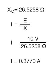
| 60 | 26.5258 |
| 120 | 13.2629 |
| 2500 | 0.6366 |
Please note that the relationship of capacitive reactance to frequency is exactly opposite from that of inductive reactance.
Capacitive reactance (in ohms) decreases with increasing AC frequency. Conversely, inductive reactance (in ohms) increases with increasing AC frequency. Inductors oppose faster changing currents by producing greater voltage drops; capacitors oppose faster changing voltage drops by allowing greater currents.
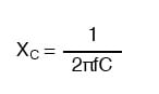
As with inductors, the reactance equation’s 2πf term may be replaced by the lowercase Greek letter Omega (ω), which is referred to as the angular velocity of the AC circuit. Thus, the equation XC = 1/(2πfC) could also be written as XC = 1/(ωC), with ω cast in units of radians per second.
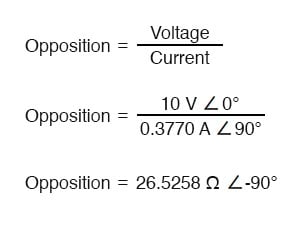
Alternating current in a simple capacitive circuit is equal to the voltage (in volts) divided by the capacitive reactance (in ohms), just as either alternating or direct current in a simple resistive circuit is equal to the voltage (in volts) divided by the resistance (in ohms). The following circuit illustrates this mathematical relationship by example:
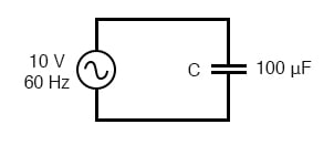
Capacitive reactance.
However, we need to keep in mind that voltage and current are not in phase here. As was shown earlier, the current has a phase shift of +90° with respect to the voltage. If we represent these phase angles of voltage and current mathematically, we can calculate the phase angle of the capacitor’s reactive opposition to current.
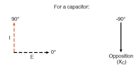
Voltage lags current by 90° in a capacitor.
Mathematically, we say that the phase angle of a capacitor’s opposition to current is -90°, meaning that a capacitor’s opposition to current is a negative imaginary quantity. (See figure above.) This phase angle of reactive opposition to current becomes critically important in circuit analysis, especially for complex AC circuits where reactance and resistance interact.
It will prove beneficial to represent any component’s opposition to current in terms of complex numbers, and not just scalar quantities of resistance and reactance.
REVIEW:
- Capacitive reactance is the opposition that a capacitor offers to alternating current due to its phase-shifted storage and release of energy in its electric field. Reactance is symbolized by the capital letter “X” and is measured in ohms just like resistance (R).
- Capacitive reactance can be calculated using this formula: XC = 1/(2πfC)
- Capacitive reactance decreases with increasing frequency. In other words, the higher the frequency, the less it opposes (the more it “conducts”) AC current.
RELATED WORKSHEETS: